
Optical Transport for 5G Mobile Network: Challenges and Solutions
Jim Zou, Jörg-Peter Elbers, ADVA Optical Networking SE, Martinsried/Munich, Germany
Abstract
As 5G roll-out accelerates globally, the mobile network operators are facing more heavy lifting over the fixed transport infrastructure, carrying not only broadband but also time-critical traffic between the data center and antenna sites. The fundamental question is what the options are and how best to design the transport network, with the goal that any solution must be cost-saving and future-proof. This article therefore reviews optical 5G transport challenges and feasible solutions, and we discuss how the optical underlay and the transport protocol can be used to consolidate future front- and backhaul traffic on an optical network infrastructure.
1. Introduction
5G has the ambition to be more than just a new radio technology, instead, it is going to serve as an enabler for a broad range of applications and vertical markets. This ambitious goal is set to address three major usage scenarios, including enhanced mobile broadband (eMBB), ultra-reliable and low latency communications (uRLLC), and massive machine type communications. In other words, the 5G is supposed to provide every end user – no matter human or machine – with a much faster and more reliable wireless network to deliver tactile and personalized communication services.
5G is not a monolithic system but a flexible platform developed over a sequence of releases in 3GPP. Release 15 laid the foundation and has been commercially deployed. It focuses on eMBB for mobile and fixed-wireless access. Standardization of Release 16 has been finished in July 2020 [1], while the timeline of Release 17 has been just agreed in the pipeline. Release 16 brings, amongst other things, support for industrial IoT, enhancements for uRLLC, improved positioning, and satellite access. Future releases are expected to deliver feature expansions necessary to realize the full 5G vision.
Checking the reality of current 5G rollouts globally, most of the mobile network operators (MNOs) are first building the radio heads, and tend to upgrade the radio access network (RAN) only when needed. Clearly, mobile network operators must invest a significant amount of their budgets to acquire new spectrum as well as NR radio equipment, leaving much smaller amount behind for the transport network. In the initial phase, this difficulty was even amplified by the fact that there was no imminent revenue and little need for additional bandwidth from upgrading the transport infrastructure. However, with the ramp-up of global 5G deployments, especially the adoption of 5G Standalone (5G SA) architecture that supports full set of 5G services, MNOs are facing more challenges while trying to keep the cost as low as possible in the RAN.
Looking at the RAN transport, although multiple options exist to connect remote cell sites to their central office, fiber offers highest capacity, longest reach, and immunity against interference and bad weather. In areas where no fiber is available or too expensive to be built, other transport solutions – especially microwave – will continue to be used. That being said, for future 5G RAN deployments, the number of fiber-connected radio sites is expected to increase significantly. This paper presents an overview of the optical transport for the 5G RAN.
2. 5G RAN disruption
3GPP has identified eight possible functional splits (FS) and associated interfaces since Release 14 for the 5G RAN architecture [2], also known as NG-RAN, consisting of the 5G Core Network (5GC) and 5G radio base station gNB. The gNB can be further broken down to three functional blocks, namely a central unit (CU), a distributed unit (DU), and a radio unit (RU), whereas in the 4G RAN only a single functional split is specified between the central BBU and remote RRH, as depicted in Figure 1.
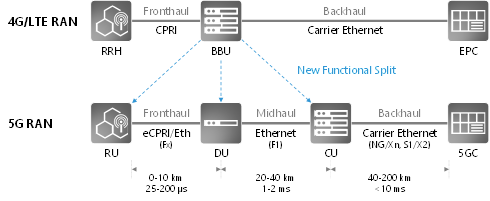
Figure 1. 5G RAN architecture and decomposition
All real-time functions are concentrated in the RU and DU, which makes the F1 interface very similar to the backhaul in terms of data rate and transport characteristics. For the Fx interface, multiple implementation options are possible. It may require 4-5 times higher data rate than the one of the F1 and backhaul interface. More importantly, the eCPRI specification defines an IP/Ethernet layer for Fx transport, as well as latency and synchronization requirements for different service classes and radio configurations [3]. This natively opens up a huge potential to leverage the well-established market scale of Ethernet equipment for the fronthaul transport, and inherits the existing Ethernet protocols for Operations, Administration, and Maintenance (OAM), Control and Monitoring (e.g. SNMP), as well as synchronization.
The trade-off of employing different split options in RAN deployments, or placement of the CU, DU, and RU, is not a clear cut. There is no one-fit-for-all choice, but such a functional decomposition offers more flexibility to design and deploy the transport network. For instance, in large cell sites leveraging carrier aggregation or Coordinated Multi-Point (CoMP), DU and CU can be collocated or integrated to optimize radio resource management. In mm-wave or small cell applications, radio heads may instead integrate the RU and DU.
On the other hand, application demands also indirectly determine or influence the position of radio functions as well. Generally, it is advisable to follow the principle “centralize what you can and distribute what you must”. This is easiest if the latency is not critical. Very low and ultra-low latency applications, though, will require computing at the network or cell edge. DU and CU processing is needed beforehand to facilitate user plane access.
Ultimately, a flexible RAN architecture may support different configurations simultaneously and use radio carriers, frequency bands or network slices to separate them.
3. Transport requirements and challenges
3.1. Bandwidth
The most important transport requirement is the fronthaul capacity per site. In the 5G RAN, the fronthaul throughput generally scales with the actual user traffic on the air interface plus a certain amount of overhead which depends on the particular functional split. Figure 2 depicts the peak transport bandwidth for a single radio sector versus the number of MIMO layers, plotting different required data rates of the Fx and F1 interface for either a 100Mz Sub-6GHz or a 400MHz mm-wave carrier. It shows that the transport bandwidth is proportional to the RF bandwidth and the Fx interface needs approximately 4 times more capacity than the F1 interface. For the summation over multiple sectors and radio sites, NGMN suggests an averaging approach, as it is unlikely that all radio units operate at peak load simultaneously [4]. The required transport bandwidth will also fluctuate over time and largely depend on the radio configuration and user traffic load.
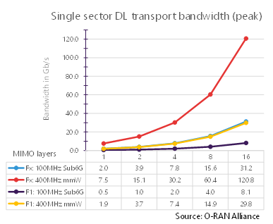
Figure 2. Transport bandwidth comparison between F1 and Fx split
Due to the variable bit rate traffic, the 5G fronthaul can eventually benefit from a packet-based transport solution which enables statistical multiplexing. It is foreseen that 10 to 25 Gbit/s optical interfaces will be adequate for 5G fronthaul in the near term [5]. At large cell sites with multiple RUs, it is feasible and beneficial to aggregate fronthaul traffic to 100 Gbit/s between Cell Site Gateways (CSGs) and DU sites.
3.2. Latency
Latency becomes not only critical, but also an extremely key variable in the 5G transport. For different service types (e.g. eMBB, URLLC, and mMTC), or vertical applications like IoT, industrial, and automobile, different latency budgets are required.
It can be viewed from two aspects: first is user latency in the order of millisecond, measured between the egress of the User Plane Function and the user equipment, and second is latency in relation to processing protocols, such as Hybrid Automatic Repeat Request (HARQ). Delays over the fronthaul interface can lead to performance inefficiency on the RAN Physical layer, and this leads to a stringent latency requirement in the order of 50 to 250 µs round trip time (RTT) between RU and DU. The light propagation time in the fiber is approximately 5 µs/km, which dominates the end-to-end latency. When using Ethernet transport equipment, queuing and buffering also introduce latency from a few microseconds to tens of microseconds, depending primarily on the packet length and line rate. Similar latency contributions also arise when using TDM-based networks, such as the passive optical network (PON) or optical transport network (OTN). Since the forward error correction (FEC) will be largely inevitable for the interface at 25 Gbit/s and beyond, the latency of FEC processing needs also to be taken into account.
However, what is more important is the determinism of latency. The variation in the One-Way Delay (OWD) of packets is called “jitter” (or “delay variation”). Fronthaul packets transported in Ethernet need to arrive within a certain time window at the ingress of radio equipment [6]. Given that the same Ethernet interface may distribute timing information, such as IEEE 1588 Precision Time Protocol (PTP), PDV will result in time error.
4. Optical layer options
As mentioned in the introduction, though it might be quicker to deploy the RAN transport through microwave, MNOs give more considerations to fiber. Apart from performance advantages, optical transport can provide a unified solution for small cells, macro cells, and massive MIMO for both 4G and 5G services. It supports a variety of Ethernet interfaces from 1 to 100 Gbit/s, and even beyond. This unfolds the use of Ethernet Network Interface Devices (NIDs) over a common optical underlay.
Different optical layer options for 5G transport exist, from which operators will likely have to address different network scenarios and use a mix of solutions.
Grey optics are the most flexible and cost-efficient solution in fiber-rich scenarios, where the RU and DU/CU are linked up by direct dark fibers per physical port. The IEEE and other MSAs have defined a variety of interfaces for reaches of FR (2 km), LR (10 km), ER (40 km), and ZR (80 km).
Wavelength division multiplexing (WDM) solutions allow the best exploitation of the fiber capacity and can be deployed as passive, semi-active or active solutions. Passive solutions use pluggable interfaces on both ends, while semi-active and active solutions use transponders on one and both ends, respectively. Dense WDM (DWDM) offers the highest fiber capacity and distance, whereas LAN-WDM and coarse WDM (CWDM) solutions leverage data center optics and can be more cost-effective, if shorter distances and lower fiber capacities are acceptable. An extended LAN-WDM and a medium WDM (MWDM) derivative with 12 wavelengths are in discussion (e.g. O-RAN Alliance, ITU-T G.owdm) to address antenna configurations with 3 sectors and 2 frequencies over a single fiber. However, so far there is no consensus on beyond 25 Gbit/s per lane for LAN-WDM or MWDM.
Time division multiplexing passive optical network (TDM-PON) exploits the fiber-to-the-x (FTTx) technology and is especially interesting in areas where such technology has already been deployed. The high 5G transport bandwidth will require the use of NG-PON2 or next-generation high-speed PON technology at 25 or 50 Gbit/s. While F1 transport is feasible with common PON technology, Fx transport requires a smaller quiet window for ONU detection and a coordinated dynamic bandwidth allocation algorithm (CO-DBA) to meet the stringent Fx latency and timing requirements. Both are currently in discussion in research and standardization.
Figure 3 depicts all three aforementioned optical layer options.
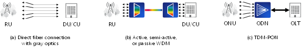
Figure 3. Optical layer options for 5G RAN transport
5. Transport protocol options
With the introduction of F1 and Fx interfaces, 5G front- and mid-haul traffic can be encapsulated in Ethernet frames, either directly or via eCPRI. Using IEEE1914.3-2018 radio-over-fiber encapsulation, legacy CPRI fronthaul traffic can also be transported over Ethernet, positioning Ethernet as convergence layer for consolidating back-, mid-, fronthaul and possibly other packet traffic. The IEEE802.1CM standard leverages Carrier Ethernet and defines new time-sensitive Ethernet transport profiles for fronthaul traffic, taking both CPRI and eCPRI requirements into account, such that frame delay variations of time-sensitive fronthaul traffic can be minimized by strict priority scheduling and optionally preempting lower priority traffic. Additional means such as the asynchronous time window approach or synchronous scheduling of time-sensitive traffic can further reduce latency and frame delay variation in the optical transport network, leading to reduced playout buffers at the terminal [7].
Layer 1 TDM schemes such as an optical transport network (OTN) with 1.25Gb/s or FlexE with 5Gb/s tributary slot granularity are also being discussed as optical x-haul options. FlexE (or G.mtn for metro transport network) perform TDM multiplexing and switching on the Ethernet physical coding sublayer (PCS). Whereas TDM schemes practically eliminate delay variations and reduce latency to a sub-hundred microseconds (OTN) and sub-microsecond scale (FlexE), they lack statistical multiplexing and fine granular traffic management capabilities.
Another rising yet critical requirement from the 5G transport protocol is to deliver timing to the RU. Conventionally, the global navigation satellite system (GNSS) at the cell site provides the reference of pulse per Second (PPS) and Time of Day (ToD), but access to the GNSS satellite signal cannot be guaranteed at all times, and it is vulnerable to the weather condition and even at risk of signal spoofing. Alternatively, the frequency and time information can be distributed from one central source through the network. ITU-T specifies Synchronous Ethernet (SyncE) to transfer a synchronization signal between network elements. It relies on a bit-level clock recovery at each hop and is highly robust for long-term frequency distribution, but it only provides frequency synchronization and every node in the sync path requires physical-layer support for SyncE. Complementing SyncE, the IEEE 1588 PTP [8] provides a mechanism for end-to-end phase and time alignment, as well as frequency distribution if SyncE is not available. However, as a packet-based Layer 2/3 protocol, the performance of PTP can be extremely dependent to the PDV across network elements. ITU-T SG15/Q13 recommends use of SyncE and PTP for 5G fronthaul solutions in ITU-T G.8275.1.
6. Conclusion
Putting all these facts together, Figure 4 summarizes all the different layering options for the optical 5G transport.
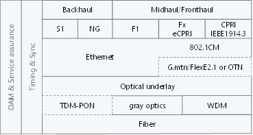
Figure 4. 5G transport layer stack
While Ethernet becomes the converged transport protocol from backhaul to fronthaul, TDM-PON, FlexE and OTN add additional protocol layers. It is worth noting that there is no one-fits-all transport solution. Depending on the available fiber infrastructure, different optical underlay technologies and network topologies (e.g. point-to-point, tree, ring) can be adopted, either standalone or in combination. In any case, an accurate distribution of timing and synchronization information is essential. Operations, administrations and maintenance as well as service assurance functions are necessary for low operational overhead in the deployed solution.
Acknowledgement
This work was supported by the European Union’s Horizon 2020 Research and Innovation Program under Grant Agreement No. 871900 (5G-COMPLETE).
References
1. “Release 16 Description; Summary of Rel-16 Work Items,” 3GPP Tech. Rep. TR21.916, 2020.
2. “Study on new radio access technology: Radio access architecture and interfaces,” 3GPP Tech. Rep. TR38.801, v14.0.0, 2017.
3. “Common Public Radio Interface: Requirements for the eCPRI Transport Network,” CPRI Specification (2018), http://www.cpri.info/spec.html.
4. NGMN Alliance, “5G RAN CU - DU network architecture, transport options and dimensioning,” Public Deliverable, v1.0, Apr. 2019.
5. P. Sehier et al., “Transport evolution for the RAN of the future [Invited],” J. Opt. Commun. Netw., vol. 11, no. 4, B97–B108, Apr. 2019.
6. O-RAN Alliance, “O-RAN Fronthaul Control, User and Synchronization Plane Specification,” O-RAN Specification, v5.0, Nov. 2020.
7. S. Bjørnstad et al., “Minimizing Delay and Packet Delay Variation in Switched 5G Transport Networks”, J. Opt. Comm. Netw., vol. 11, no. 4, B49–B59, Apr. 2019.
8. “Precision Clock Synchronization Protocol for Networked Measurement and Control Systems,” IEEE Std. 1588-2019.
Jim (Shihuan) Zou (M’16) received his B.Eng. degree in communication and information engineering and M.Sc. degree in electrical circuits and systems from Shanghai University, China, in 2008 and 2011, respectively. In 2015, He received the PhD degree from the Eindhoven University of Technology, The Netherlands, where he conducted the fiber-wireless research work. Since 2016, he is with ADVA Optical Networking SE, Germany, currently as principal engineer leading EU research projects in the area of next-gen optical access. He actively participates in the O-RAN Alliance and ITU-T SG15 for RAN standardization contributions. He is also a core member of the Access Solution team under Product Line Management, supporting product design and business development.
Jörg-Peter Elbers (M’00–SM’18) is responsible for technology strategy, applied research, standardization and intellectual property at ADVA. He has more than 20 years of experience in the optical networking industry. Prior to joining ADVA, Jörg held senior technical and leadership roles at Ericsson, Marconi and Siemens. He earned a Dipl-Ing. and Dr.-Ing. degree in electrical engineering from Technical University Dortmund, Germany. Jörg is senior member of the IEEE, heads the German VDE ITG expert committee on communications, and serves on the steering board of the European technology platform on networks (Networld2020). He was technical and general co-chair of OFC 2017 and 2019, respectively, and is member of the European management committee of ECOC. Jörg authored and co-authored more than 150 papers, 5 book chapters, and 20 patents.
Subscribe to Tech Focus
Join our IEEE Future Networks Technical Community and receive IEEE Future NetworksTech Focus delivered to your email.
Article Contributions Welcome
Submit Manuscript via Track Chair
Author guidelines can be found here.
Other Future Networks Publications
IEEE Future Networks Tech Focus Editorial Board
Rod Waterhouse, Editor-in-Chief
Mithun Mukherjee, Managing Editor
Imran Shafique Ansari
Anwer Al-Dulaimi
Stefano Buzzi
Yunlong Cai
Zhi Ning Chen
Panagiotis Demestichas
Ashutosh Dutta
Yang Hao
Gerry Hayes
Chih-Lin I
James Irvine
Meng Lu
Amine Maaref
Thas Nirmalathas
Sen Wang
Shugong Xu
Haijun Zhang
Glaucio Haroldo Silva de Carvalho