
Overcoming 5G Millimeter Wave Black Holes
Dushmantha N.P. Thalakotuna (IEEE Member), School of Engineering, Macquarie University, Australia, Karu P. Esselle (IEEE Fellow), School of Electrical and Data Engineering, University of Technology Sydney, Australia
IEEE Future Networks Tech Focus, Volume 3, Issue 3, November 2019
Abstract
Millimeter wave frequency bands are expected to play a significant role in providing higher data rates for 5G users. One of the main drawbacks of millimeter wave spectrum is the building blockages or penetration losses (in walls or glass windows) to indoor environment. Hence 5G outdoor base stations or otherwise known as gNodeBs (gNB) can fail to provide the required capacity for indoor users unless indoor base stations are in use. Deployment of indoor base stations such as femto or pico cells and connecting them into backbone network using cables can be expensive and time consuming. Thus, an inexpensive and rapidly deployable solution that can provide excellent indoor coverage will greatly benefit indoor users as well as operators. In this paper, we present and discuss such a solution referred to hereafter as a 5G extender. The concept of operation and system level architecture of the 5G extender is discussed with a main focus on highlighting challenges associated with antenna technologies to be used in this system.
1. Introduction
One of the main use cases for 5G is enhanced mobile broadband (eMBB). The data rates of eMBB are 100 Mbps in the downlink (DL) and 50 Mbps in the Uplink (UL) in a Dense Urban test environment [1]. eMBB is best catered by mm-wave (mmW) instead of Sub 1-GHz spectrum or 1- 6 GHz spectrum due to the wider channel size (1 GHz) allowed in mmW bands.
A range of bands from 24 GHz-86 GHz are under discussion to be harmonized internationally for 5G mmW spectrum as part of ITU WRC-2019. Despite the outcome of harmonised band, one of the key challenges yet to be addressed is how one would work around the propagation loss and building blockage at mmW frequencies. This greatly hinders the ability of 5G gNBs to provide indoor coverage and capacity at mmW frequencies.
Measurements in [2-3] reported 40dB penetration loss through tinted glasses and a 28dB penetration loss through brick at 28 GHz. Such high penetration losses indicate, communication from gNBs to an indoor environment cannot be guaranteed let alone achieving eMBB speeds of 100 Mbps, which is almost impossible. Reported penetration losses from outdoor to indoor even at 3.5 GHz spectrum exceed 10 dB [4] making it challenging for gNBs to provide indoor coverage when using 1 – 6 GHz spectrum.
It is reported over 80% of 4G services take place indoors and the numbers are to be increased for 5G services [4]. This poses a great challenge on how 5G provides indoor users a similar user experience to outdoors, because 5G gNBs alone will clearly fail to provide a seamless transition from outdoor to indoor. Solutions include using indoor 5G base stations and/or using 5G customer premises equipment (CPE) [5]. However, these solutions may incur extended setup times due to approvals and can also be costly. In the interim, or in many cases long-term, a low cost, easy to deploy solution to address this challenge will greatly benefit users and operators both.
In this paper, we present a low-cost, rapidly deployable 5G outdoor to indoor extender that can be used to boost the indoor coverage and capacity. Such a system will facilitate the eMBB service targets to be met not only outdoors but also in indoor environments with minimum cost and setup time.
The aim of this communication is to present the concept at system level and highlight the challenges that needs to be addressed by antenna technologies to be used in such 5G extender system.
2. Concept of Operation
The concept of operation is shown in Figure 1. The 5G extender system is mounted on an outside glass panel of a window in a building although other locations are also possible. The function of the extender is to amplify and retransmit the signal from a gNB to the indoor environment in the downlink (DL). In the uplink (UL), the user signal will be amplified and retransmitted to the gNB.
To achieve the maximum advantage, the 5G extender should support both Frequency Division Duplexing (FDD) and Time Division Duplexing (TDD). FDD imposed requirements necessitate the need to meet the required 5G bandwidths in 1-6 GHz and mmW bands by the 5G extender. TDD imposed requirements will enforce a processing delay specification on the 5G extender system. The eMBB service minimum user plane latency is 4ms. Hence the 5G extender should introduce the minimum time delay during amplification and transmission, for example in the range of 2-3 ms, to meet eMBB user plane latency requirement.
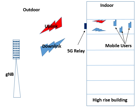
Figure 1: 5G extender operating concept
Apart from aforementioned functional requirements, the next major considerations are on Space Weight and Power (SWaP) aspects. The 5G extender system needs to have a small footprint and light in weight since it is proposed to be window mounted. Small footprint will provide less visibility and less disruptions to the aesthetics and appearance of buildings when it is mounted on windows in buildings or houses. Lightweight will have less stress on glass and can provide easier mounting mechanisms. Power is required to provide the amplification for UL and DL signals.
3. System Architecture
This section describes the system level architecture for the 5G extender system. The subsystems inside the 5G extender system is shown in Figure 2. Antenna systems will provide the communication links to gNB and users. The signal conditioning subsystem will provide the required filtering and amplification. The signal conditioning function can be performed using digital or analog signal processing. While digital signal processing may provide good signal conditioning in terms of filtering, analog to digital signal conversions may introduce additional delays. Hence it is appropriate to use analog signal processing in order to meet the user plane latency requirements.
The antenna system comprises of a.) outdoor antenna system and b.) indoor antenna system. The outdoor antenna system facing outdoors will create and maintain the communication link with the gNB. The indoor antenna system facing indoors will communicate with 5G new radio (NR) user terminals.
The antenna system should support downlink and uplink as well as spatial multiplexing. To provide a full duplex communication, simplest realization would be to use two separate (TX and RX) antennas in each outdoor and indoor antenna subsystems i.e. outdoor antenna system will have a downlink antenna and an uplink antenna. Similarly, indoor antenna system will have a downlink and an uplink antenna. This will provide a distinct downlink channel and an uplink channel enabling full duplex communication. Spatial multiplexing is desired to increase the capacity; this can be achieved by using dual polarized (+45 and -45) antenna elements.
In the DL the base station signal is received by the outdoor antenna subsystem and then amplified and filtered before it is retransmitted from indoor antenna subsystem. The signal goes through the reverse order in the UL.
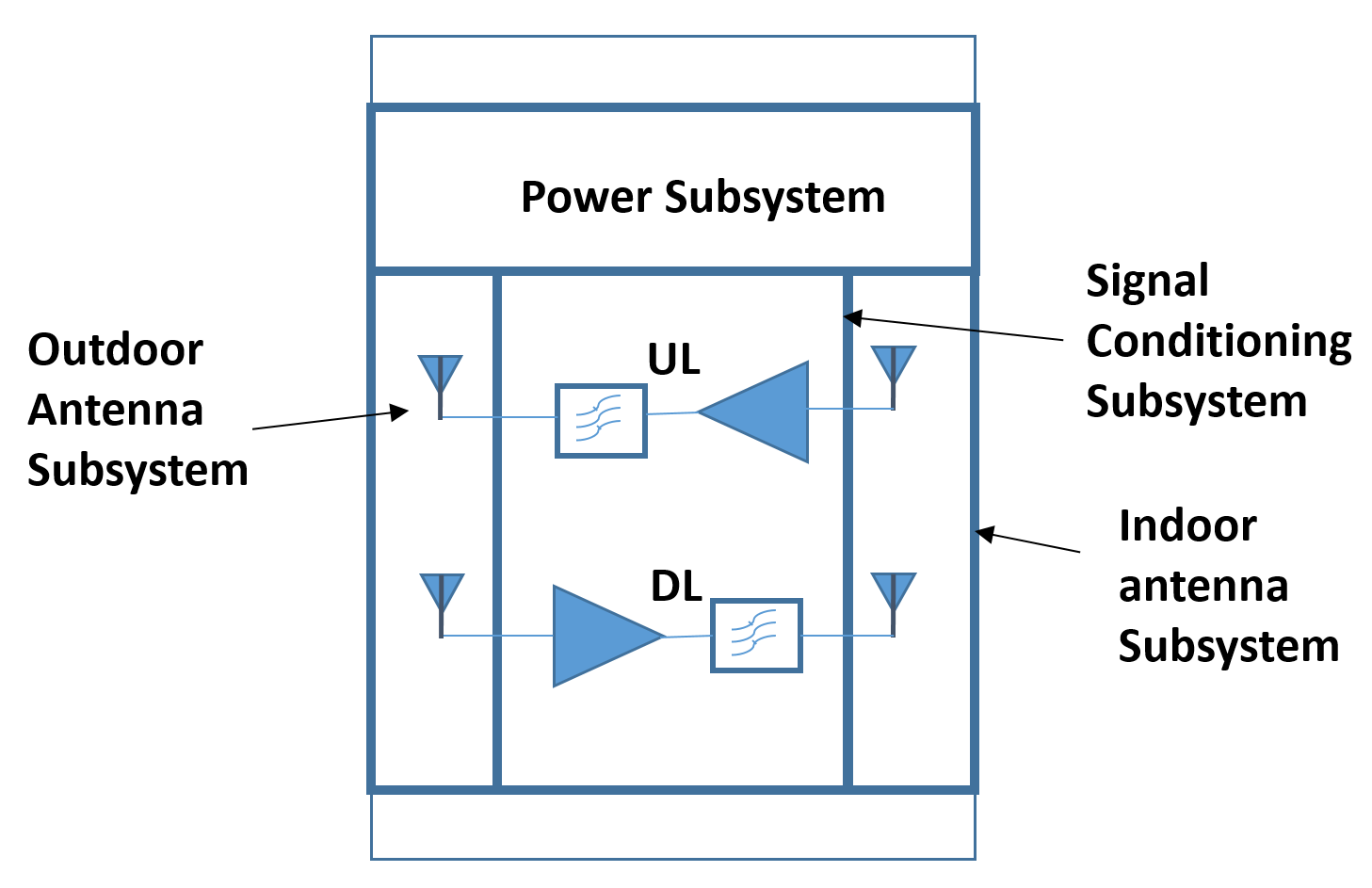
Figure 2: 5G extender subsystems
The power subsystem will provide power to signal conditioning subsystem and antenna sub system to perform amplification and beam steering respectively. Since the 5G extender is mounted outside the window, it is difficult to access a power outlet using a cable (because most building do not have power outlets outside). Hence a wireless power transfer module mounted inside the window is used for powering the 5G extender. The extender unit may include an optional rechargeable battery to maintain its function during power interruptions. Also optionally, this battery may be charged using outdoor solar panels attached to the building or emerging transparent solar cells that are integrated to window glass. In some locations, solar charging during daytime may be sufficient to run the external unit whole day and night so powering the unit from mains using wireless power transfer through glass may not be necessary at all.
4. Antenna System Challenges
The focus of this section is to understand the challenges associated with developing low cost antenna systems for the 5G extender.
Directivity and Beam steering
The outdoor antenna subsystem maintains a communication link with the gNB. A higher SNR improves the quality of the link providing higher data rates. To achieve higher SNR, high gain antennas are needed. The base station antenna gain is not at the system designers’ discretion but the outdoor antenna system can be made a directive high gain antenna. If the gNB uses beamforming or has massive MIMO capability, the link will understandably provide better SNR due to the additional gain from the base station beamforming.
In practice, the 5G base station can be in any arbitrary direction relative to the 5G extender. For example, the 5G extender could be on a window of a high rise building while the base station is at a much lower altitude and off its vertical plane (orthogonal to window) as in Figure 1. Therefore, the beam should be steerable in a large conical region to point it towards the base station that sends best signals to this 5G extender system.
The conventional high gain antennas used for mmW point to point links are horns or dishes. While such solutions are feasible, it’s important to consider aesthetics, impact on building architectural integrity, potential violation of council/local government regulations and ergonomics during installation. The outdoor antenna beam should be electrically steerable and will be steered and locked towards the base station to obtain the best possible SNR during installation. Having to do mechanical alignments can result in complex mounting solutions and high initial setup costs.
Conventional horn or dish type antennas will require mechanical movements during installation to point the beam to the base station. Also horns or dishes can be bulkier compared to planar antenna types such as patch arrays or slot arrays. Horn or dish antennas with motorized remote-control are available (e.g. motorized satellite TV dish antennas) but they are even bulkier and more expensive. These features can make it impractical to use such antennas in a low profile, light weight 5G extender system.
A patch or slot antenna array with the beam steering ability can satisfy the low profile and compactness requirements and provide a high gain due to array factor. Low profile antennas such as steerable phased arrays [6], steerable patch antenna arrays [7], steerable slot arrays [8] or beam steering dielectric resonator antennas [9] stand out as good candidates for the outdoor antenna system. While there are other low-profile steerable antennas such as those in [10-12], with features such as beam steering mechanism, scanning range and antenna size may not be optimum for using them in the outdoor antenna system.
The cost of the antenna subsystem needs to be low in order to keep the 5G extender inexpensive. The printed antennas will make the antenna cost cheaper but the cost of the antenna system is mostly driven by the steering mechanism. The antenna needs to be steered and locked only once during installation, hence using an electronically steerable solution is an overkill and will increase cost. Either a simple mechanical beam steering solution or the use of near-field metasurfaces to steer the beam [9], manually or electrically with remote control, can result in a low cost antenna system.
The indoor antenna system requirements are much lenient and needs only a wider beam to provide more coverage to the indoor environment. In theory, a beamforming array can also be used as the indoor antenna, but this would require intelligence to be built in the extender providing additional signal processing delays. The eMBB service has a 4ms latency requirement, hence for simplicity it’s desirable to have only analog processing in the 5G extender system. Therefore, a simple low profile patch antenna is a good candidate for the indoor antenna system.
Polarization
Making use of the principle of decoupling between two orthogonally polarized electromagnetic waves, current (and potentially future) base station antennas use +45 and -45 slant elements to provide polarization diversity. This is used to increase the capacity in a 2 layer MIMO system. The antenna systems in the 5G extender should support the polarization diversity in order provide this capacity increase by having dual polar antenna elements. In other words, each antenna (TX/RX) in the Outdoor Antenna Subsystem should be dual polarized, with two decoupled ports for the two polarizations (+/- 45o).
Each of the outdoor antenna polarization should match the corresponding polarization of the 5G base station antenna to maximize the polarization gain and to avoid cross-interference between the two data streams with orthogonal polarizations. This should hold even for steered beams of 5G extender system. However, it is very challenging for an array antenna to maintain constant polarization (and the ability to reject cross polarization leaking into it) during beam steering.
The polarization of a conventional antenna array changes with beam steering i.e. if the array has a linear polarization in the broadside beam, it becomes more elliptical as the beam steers. As a result, +45 or -45 polarized antenna array can become vertically or horizontally or elliptical polarized when its beam is steered towards an off axis gNB, as shown in Figure 3. The gNB1 is located in broadside direction of 5G extender and the two polarizations align between the extender and the gNB. Such alignment is optimum as it minimizes the crosstalk or leakage between the two data streams. When gNB is off broadside as in gNB2 but in the same horizontal plane, the polarizations of the beam of 5G extender do not exactly align with those of the base station resulting in cross-polarization leaking into the extender and degrading capacity. In gNB3 direction, the steered beam has an elliptical polarization, and again cross-polar interference and degraded capacity will become imminent.
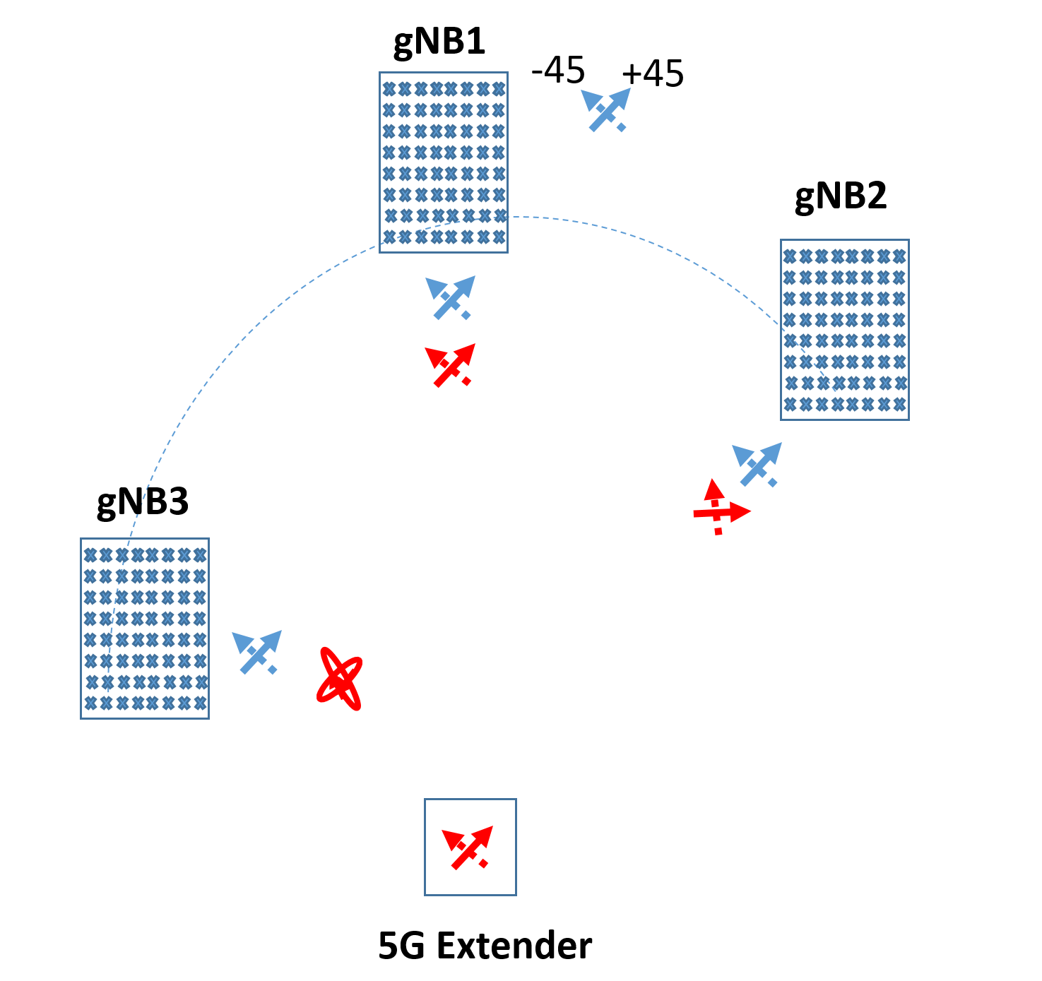
Figure 3: Change of polarization with beam steering
It’s important to characterize this polarization of the steered beam to understand cross polarization leakage. The legacy method is to look at the Cross Polarization Discrimination (CPD) or otherwise referred as Cross Polarization Ratio (CPR) which measures magnitude difference between the cross-polarized pattern to the co-polarized pattern. BASTA recommendations [14] followed by most leading base station manufacturers states a minimum 8 – 10 dB CPD for minimum degradation on MIMO performance for legacy base station antennas. Hence, higher CPD is desirable to improve MIMO performance.
Figure 4 shows the CPD of a 4x4 patch array when the beam is steered from +55o to -55o in the xz plane. A very high CPD is achieved when the beam is pointing towards boresight (0o) but the CPD decreases as the beam is steered off axis. It is also interesting to note that the CPD of the array follows a very similar CPD profile to a single radiating patch element (which of course has a wider fixed beam with a peak at 0o). The slight differences in the two curves are due to the mutual coupling effects between patch elements in the array. Therefore, when mutual coupling effects are ignored the array will have the same CPD in the steered beam direction to its base radiating element.
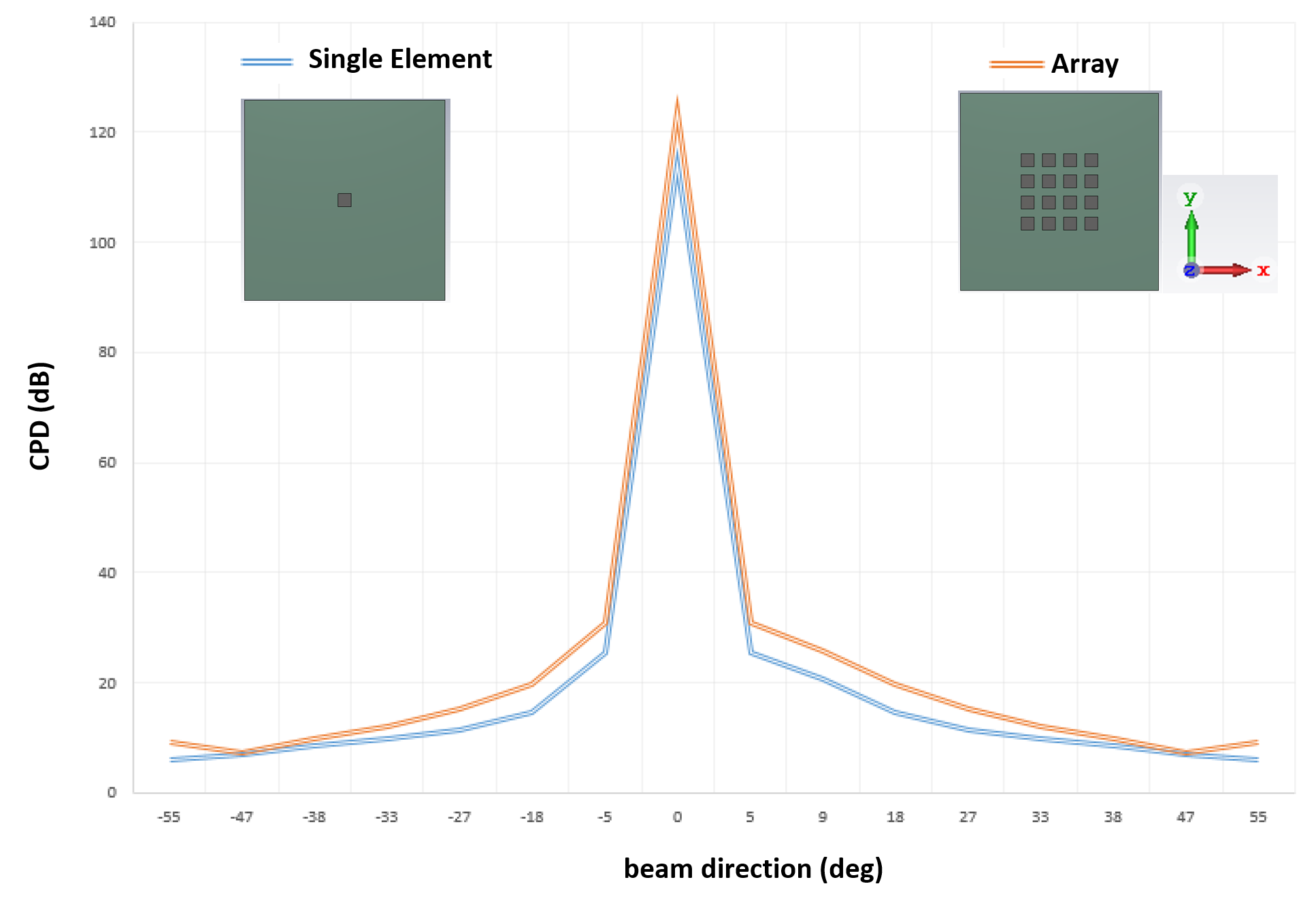
Figure 4: Comparison of CPD along 3D representation of CPD in a patch radiating element at 28 GHz
Figure 5 shows a 3D representation of the CPD of a radiating patch at 28 GHz. It can be seen the CPD is high only in broadside direction and CPD diminishes in all other directions. An array made from this patch element will also follow the same CPD profile when its beam is steered, irrespective of the technology used for steering.
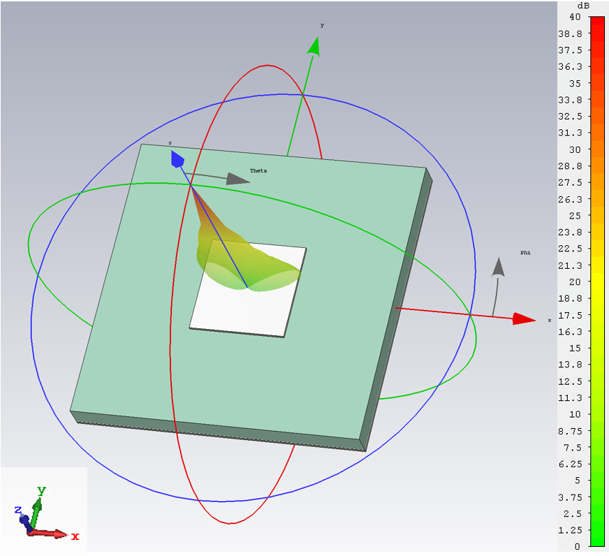
Figure 5: 3D representation of CPD from a radiating patch element at 28 GHz
Although CPD is adapted widely in base station terminology to characterize cross polarization leakage, it does not provide direct insight into the type of polarization (i.e. linear, elliptical or circular) of the radiated electric fields. Axial ratio (AR) on the other hand provides such insights. The higher dB values in AR represent a linear polarized wave whereas a lower dB values represent an elliptically polarized wave. Zero dB AR means a circularly polarized wave.
Similar to CPD it holds that the AR of the array follows its base element AR. Therefore, it is important for a base element to have linear polarization in all possible gNB directions in order for the array to have a linearly polarized electric field in the far field. In addition, and more importantly, that two linear polarization vectors of the extender antenna must align with the two desired (+45 or -45) polarization vectors of the gNB. More precisely, ideally the polarization vector of the linearly polarized wave radiated towards the gNB by one input of the extender antenna should align with the linear polarization vector of the wave received by the +45 input of the gNB antenna. The same is true for the other input of the extender antenna and -45 input of the gNB. In practice this means that the -45o (i.e. cross-) polarization level radiated by one input of the extender antenna towards the gNB should be at least 20dB (or whatever the threshold set during network planning) weaker than the +45o (i.e. co-) polarization radiated by the same input towards the gNB for all possible directions of gNB antenna locations relative to the extender antenna. Of course, the same requirement should be met for the other input of the extender antenna as well, for -45o co-polarization.
Figure 6 shows the axial ratio (AR) and the tilt angle (ᴦ) of the polarization vector in the xz plane (Phi=0) for a typical patch antenna element at 28 GHz. It can be seen that in broadside direction (Theta=0) the AR is very high and the tilt angle is 90 degree indicating it is a vertically polarized wave. This patch antenna can be rotated about its axis by 45 degrees to receive (and transmit) one polarization of the base station antenna (say +45) while rejecting its orthogonal polarization (-45). Another patch antenna rotated in the opposite direction by 45 degrees can deal with the orthogonal (-45) polarization the same way while rejecting +45. It is possible to integrate two such orthogonally polarized elements into one dual-polarized element with two sufficiently decoupled +/- 45 outputs. The real challenge is something else. Note that away from the broad side direction the AR is decreasing making the radiated wave elliptical. At the same time the tilt angle changes meaning that polarization ellipse rotates as the beam is steered.
For the indoor antenna system, a dual-polarized radiating element (with two decoupled inputs/outputs, one for each polarization) can be used. Since there is no beamforming involved, an element with good linear polarization characteristics within the 3dB beamwidth is sufficient for the indoor antenna.
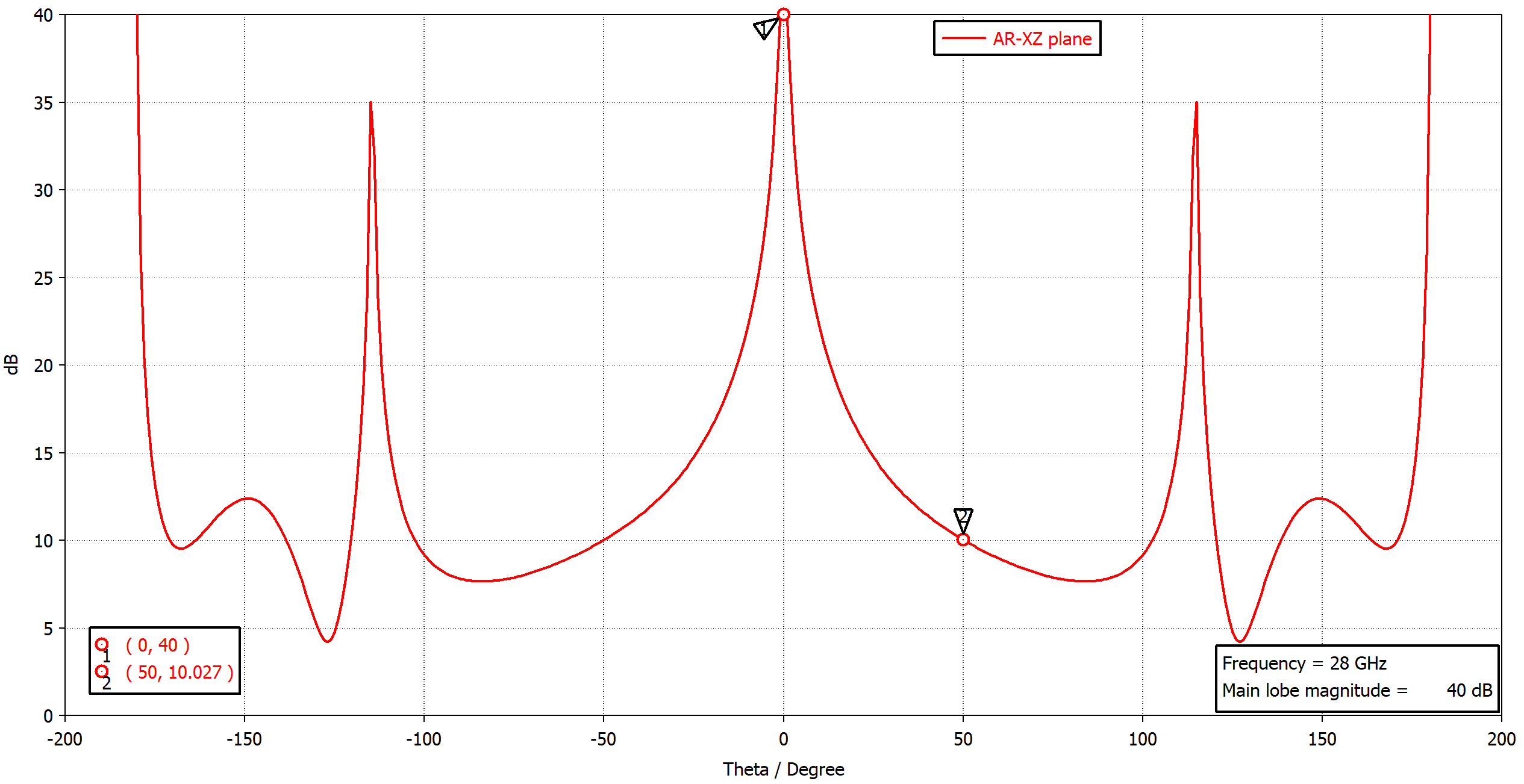
(a)
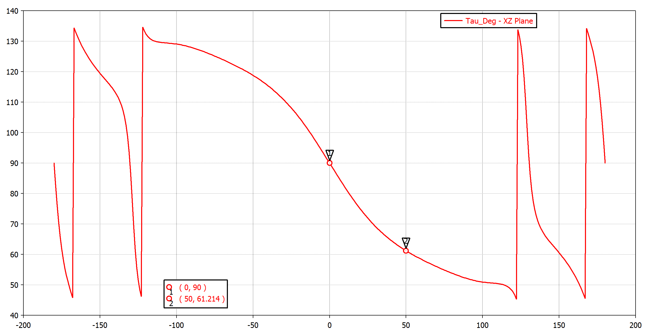
(b)
Figure 6: (a) Axial ratio in XZ plane (b) tilt angle (ᴦ) of polarization ellipse in XZ plane for the patch antenna element at 28 GHz
Bandwidth
While 5G spectrum still needs to be harmonized, the 28 GHz and 39 GHz appear to be the most widely discussed spectra for 5G mmW communication. In 1-6GHz range, 3.5GHz spectrum is already in use for 5G at present. It is expected that 80-100 MHz in 3.5 GHz and 1GHz in mmW bands will be allocated per operator as contiguous spectrum. This requires the antenna system to support a few GHz bandwidth in the mmW bands. Hence, we require wideband antennas for both outdoor and indoor antennas in the 5G extender system.
Certain planar antenna arrays in literature have reported over 16% bandwidth at mmW frequencies [11-13], however their beam steering capability is limited. Hence more research and development are required for outdoor antenna systems that can perform wider-range beam scanning over a wide bandwidth. Maintaining sufficient polarization discrimination between the two orthogonal (desired co- and undesired cross-) polarizations when steering the beam of an array over a wide angular range is a challenge for which there is no solution at present, to the best of our knowledge. Current gNBs do have such features for electric beam tilt, but their angular range is very limited and not sufficient for this application. Although some research is in progress to address this challenge, demonstrated solutions are yet to appear in literature.
The indoor antenna system does not have stringent requirements in terms of beam steering, hence meeting a wide bandwidth will be less challenging. However, note that the indoor antenna is mounted facing towards the window. Due to close proximity, window glass may act as a near-field superstrate and has the potential to detune the antenna. Therefore, impact of glass as a superstrate should be taken into account during indoor antenna system design, which is not a challenge.
5. Conclusion
In this article, we’ve discussed a low-cost and easy to deploy 5G extender system architecture to extend coverage and capacity of gNBs to indoor users at mmW frequencies. This enables gNBs to meet its quality of service targets for eMBB service both outdoors and indoors. We also highlighted major challenges associated with antenna systems in such a 5G extender. It is shown that conventional antenna beam steering methods do not maintain antenna polarization when steering over a large angular range as required in this system (and potentially in other future 5G systems including massive MIMO arrays and large electronically-steered phase arrays at gNBs). This means that the orthogonally-polarized data stream (e.g. – 45o) will cross couple to the desired (+45o) data stream, potentially degrading significantly the signal-to-interference ratio and throughput in each channel as well as overall system capacity. Hence the outdoor antenna in such a system should not only have beam steering ability over a large angular range in both planes (elevation and azimuth relative to the antenna) but should be capable of maintaining good cross-polarization rejection when its beam is steered towards the gNB electronically or manually.
The same is likely to be an issue in future 5G base station antennas used in gNBs as well, if their beam is steered over a large angular range, as opposed to current conventional base station antennas where steering is small. This is likely to be a challenge irrespective of the scale of the gNB antenna (including MIMO or Massive MIMO) and the method of steering (e.g. digital beamforming, baseband beamforming and RF/IF beam forming) because it is a fundamental electromagnetic radiation challenge that cannot be easily resolved by digital or analog processing at the digital, baseband, IF or RF levels.
References
- Report ITU-R M.2410-0, “Minimum requirements related to technical performance for IMT-2020 radio interface(s), 2017.
- T. S. Rappaport et al., “Millimeter wave mobile communications for 5G cellular: It will work!” IEEE Access, vol. 1, pp. 335–349, May 2013.
- H. Zhao, R. Mayzus, S. Sun, M. Samimi, J. K. Schulz, Y. Azar, K. Wang, G. N. Wong, F. Gutierrez, T. S. Rappaport, “28 GHz millimeter wave cellular communication measurements for reflection and penetration loss in and around buildings in New York city,” IEEE International Conference on Communications (ICC), Jun. 2013.
- Indoor 5G Networks White Paper, v2.0, September 2018.
- 5G Fixed Wireless, Increasing Market Potential with Self-Install Technology White Paper, Jan 2019.
- Rashidian, S. Jafarlou, A. Tomkins, K. Law, M. Tazlauanu and K. Hayashi, "Compact 60 GHz Phased-Array Antennas With Enhanced Radiation Properties in Flip-Chip BGA Packages," in IEEE Transactions on Antennas and Propagation, vol. 67, no. 3, pp. 1605-1619, March 2019.
- K. Klionovski , M. S. Sharawi , and A. Shamim, “A Dual-Polarization-Switched Beam Patch Antenna Array for Millimeter-Wave Applications”, IEEE Trans. Antennas Propag., vol. 67, no. 5, pp. 3510–3515, May. 2019.
- P. Gregory, “Dielectric Steering of a 3D Printed Microwave Slot Array”, IEEE Antennas and Wireless Propagation Letters, vol. 17, no. 11, pp. 2141-2144, Nov. 2018.
- M. U. Afzal and K. P. Esselle, ‘‘Steering the beam of medium-to-high gain antennas using near-field phase transformation,’’ IEEE Trans. Antennas. Propag., vol. 65, no. 4, pp. 1680–1690, Apr. 2017.
- Z. Briqech, A.-R. Sebak, and T. A. Denidni, “Low-cost wideband mmWave phased array using the piezoelectric transducer for 5G applications,” IEEE Trans. Antennas Propag., vol. 65, no. 12, pp. 6403–6412, Dec. 2017.
- F. M. Monavar, S. Shamsinejad, R. Mirzavand, J. Melzer, and P. Mousavi, ‘‘Beam-steering SIW leaky-wave subarray with flat-topped footprint for 5G applications,’’ IEEE Trans. Antennas Propag., vol. 65, no. 3, pp. 1108–1120, Mar. 2017.
- C.-X. Mao, S. Gao, and Y. Wang, “Broadband high-gain beam-scanning antenna array for millimeter-wave applications,” IEEE Trans. Antennas Propag., vol. 65, no. 9, pp. 4864–4868, Sep. 2017.
- J. Zhu, C.-H. Chu, L. Deng, C. Zhang, Y. Yang, and S. Li, ‘‘mm-Wave high gain cavity-backed aperture-coupled patch antenna array,’’ IEEE Access, vol. 6, pp. 44050–44058, 2018.
- N-P-BASTA Whitepaper, Version 10.0, 17th February 2017.
 Dushmantha Thalakotuna (M’09) received his BSc. in Electronics and Telecommunication (2008) from University of Moratuwa, Sri Lanka and PhD (2012) in Electronic Engineering from Macquarie University, Australia. He has been with Commscope Australia as a radio frequency engineer (2013-2016), BAE systems Australia as a senior radio frequency engineer (2016-2017) and Thales Australia as a senior systems engineer (2017-2019). He joined School of Engineering, Macquarie University, Australia as a lecturer in 2019. His current research interests include MMICs, Reconfigurable Microwave and Millimeter wave antennas and circuits. He is the current IEEE NSW Section secretary and is a member of Antennas and Propagation Society and Microwave Theory and Techniques Society.
 Karu P. Esselle (M’92–SM’96–F’16), received the B.Sc. degree (First Class Hons.) in electronic and telecommunication engineering from the University of Moratuwa, Moratuwa, Sri Lanka, and the M.A.Sc. and Ph.D. degrees in electrical engineering from the University of Ottawa, Ottawa, ON, Canada. He has provided expert assistance to over a dozen companies,including Intel, Santa Clara, CA, USA, Hewlett Packard Laboratory, Palo Alto, CA, USA, Cisco Systems, San Jose, CA, USA, Cochlear, Sydney, Australia, Optus, Sydney, ResMed GmbH & Co. KG, Planegg, Germany, and Katherine-Werke, Rosenheim, Germany.
He is currently the Distinguished Professor of Electromagnetic & Antenna Engineering in University of Technology Sydney, Australia. Prior to this he was a Professor at Macquarie University, Sydney, Australia, a Co-Director of the WiMed Research Center, and the Past Associate Dean-Higher Degree Research of the Division of Information and Communication Sciences. He has authored over 500 research publications and his papers have been cited over 8,000 times.
Editor: Rod Waterhouse

Rod Waterhouse received his BEng, MS, and PhD in Electrical Engineering from the University of Queensland, Australia, in 1987, 1989 and 1994, respectively. In 1994 he joined RMIT University as a lecturer, became a Senior Lecturer in 1997 and an Associate Professor in 2002. From 2001 – 2003 Dr Waterhouse was with the venture-backed Dorsal Networks which was later acquired by Corvis Corporation. In 2004 he co-founded Pharad, an antenna and high performance RF-over-fiber technologies company of which he is the Chief Technology Officer. From 2003 he was also appointed as a Senior Fellow within the Department of Electrical and Electronic Engineering at the University of Melbourne. Dr Waterhouse’s research interests include antennas, electromagnetics and microwave photonics engineering. He has over 290 publications in these fields, including 2 books and 4 book chapters. Dr Waterhouse received the grade of IEEE Fellow for his work on printed antenna and microwave photonic technologies. Dr Waterhouse was an Associate Editor for IEEE AP Transactions during 2003 – 2009 and he is the Member at Large for IEEE Int. Topical Meeting on Microwave Photonics since 2016. Dr Waterhouse has been on the IEEE Photonics Society Fellow Evaluation Committee since 2013 and was a Representative of the IEEE Photonics Society for the National Photonics Initiative in 2015. In 2000, IEEE Third Millennium Medal for ‘Outstanding Achievements and Contributions’.
Subscribe to Tech Focus
Join our IEEE Future Networks Technical Community and receive IEEE Future NetworksTech Focus delivered to your email.
Article Contributions Welcome
Submit Manuscript via Track Chair
Author guidelines can be found here.
Other Future Networks Publications
IEEE Future Networks Tech Focus Editorial Board
Rod Waterhouse, Editor-in-Chief
Mithun Mukherjee, Managing Editor
Imran Shafique Ansari
Anwer Al-Dulaimi
Stefano Buzzi
Yunlong Cai
Zhi Ning Chen
Panagiotis Demestichas
Ashutosh Dutta
Yang Hao
Gerry Hayes
Chih-Lin I
James Irvine
Meng Lu
Amine Maaref
Thas Nirmalathas
Sen Wang
Shugong Xu
Haijun Zhang
Glaucio Haroldo Silva de Carvalho