
IEEE Tech Focus - May 2024
IEEE Future Networks Tech Focus
Issue 16, June 2023
In This Issue 17
- Congestion Management Techniques for Future Satellite Networks
- TDD Mode on NTN Direct to Satellite Service
- Reference Architectures for Enabling Integrated Satellite-6G Applications and Services
- QoS Optimization-based Core Network Distribution Strategy For B5G Non-terrestrial-network (NTN)
- Distributed Deep Reinforcement Learning for Latency Optimized Computation Offloading in Aerial-Assisted MEC Networks
Congestion Management Techniques for Future Satellite Networks
June 2023
Authors: Pablo Madoery, Carleton University; Gunes Karabulut Kurt, Polytechnique de Montreal, Canada; Halim Yanikomeroglu, Carleton University; Peng Hu, National Research Council, Canada; Khaled Ahmed, Satellite Systems, MDA, Canada; Guillaume Lamontagne, Satellite Systems, MDA, Canada
Future satellite networks will make intensive use of inter-satellite links and computing edge capabilities to conform communication networks in space that connect millions of users on the ground. Unlike terrestrial Internet-based networks, these new satellite networks will need to incorporate novel techniques to avoid or mitigate congestion. In this paper we describe the main features of schemes incorporating these techniques and compare their performance by means of simulations of a realistic satellite constellation. The results show the benefits of moving from reactive feedback-based schemes to proactive schemes that prevent congestion before it occurs..
TDD Mode on NTN Direct to Satellite Service
June 2023
Authors: Shaoli Kang, China Information Communication Technology Group, China; Deshan Miao, China Information Communication Technology Group, China; Shaohui Sun, China Information Communication Technology Group, China; Shanzhi Chen, China Information Communication Technology Group, China
Though the Time Division Duplex (TDD) is a typical mode in the terrestrial communication, it was seldom applied in the satellite communication. With the increasing requirements on Direct to Satellite Service (D2SS), TDD is expected to solve the problems of low frequency shortages suitable for handheld terminals. This paper tries to discuss TDD mode on Non-Terrestrial Network (NTN) to support D2SS, including advantages and disadvantages, technical challenges and also potential solutions for TDD mode.
Reference Architectures for Enabling Integrated Satellite-6G Applications and Services
June 2023
Authors: Debrabata Dalai, Indian Institute of Space Science and Technology; Sarath Babu, Iowa State University, Ames, USA; BS Manoj, Indian Institute of Space Science and Technology
Reference Architectures (RAs) play an important role in the integration of 6G terrestrial and satellite networks. In this paper, we present the essence of the reference architectural roadmap as per the Edition-3 document of the Satellite Working Group of IEEE Future Networks Initiative (FNI). We focus on an integrated virtualized 6G-satellite architecture. Further, we present one of the case studies, Space Based Hosting Service (SBHS) approach with simulation results. SBHS approach deploys the content-servers in LEO satellite to achieve the low-latency service requirements. The architecture of SBHS is a special case over Reference Architecture-3. We achieved minimum average end-to-end latency of 7.75ms for the geographical area covering India by the proposed SBHS approach.
QoS Optimization-based Core Network Distribution Strategy For B5G Non-terrestrial-network (NTN)
June 2023
Authors: Yifei Jiang, Shanghai Jiao Tong University; Zhili Sun, University of Surrey; Shufan Wu, Shanghai Jiao Tong University
Since the initial commercial deployment of 5G in 2019, the research community and industry have already started to outline their future 6G visions especially into the direction of blending the physical and the virtual worlds in the digitised society. While 5G will continue to evolve in the near future, there are also brand new technical challenges that will be mainly tackled in the context of 6G, e.g. ambient sensing, precision localisation and synchronisation, and manipulation of the radio propagation environment. In this article we highlight our 6G vision and some selected 6G-oriented research activities carried out at the 6G Innovation Centre (6GIC) of the University of Surrey. 6GIC will be a key UK-based hub for global innovation and collaboration on 6G wireless, involving governments, regulators, mobile operators, vendors, enterprises, and leading research and development centres, as 5GIC was for 5G innovation at the University. In this article we first outline some key features of our top-level 6G vision before diving into specific topics where a number of selected research items investigated at 6GIC are introduced.
Distributed Deep Reinforcement Learning for Latency Optimized Computation Offloading in Aerial-Assisted MEC Networks
June 2023
Authors: Nida Fatima and Paresh Saxena; Department of Computer Science and Information Systems, BITS Pilani, India; Giovanni Giambene, Department of Information Engineering and Mathematics, University of Siena, Italy
The ultra-low latency requirements of mission-critical applications necessitate high computation power. To accomplish this objective, multi-access edge computing (MEC) is a crucial technology that brings computation resources closer to user equipments (UE) and provides an offloading option. In situations where terrestrial MEC cannot meet the requirements, aerial-assisted MEC with unmanned aerial vehicles (UAVs) can be utilized due to their flexible deployment and enhanced coverage. However, for a latency-optimized optimal offloading strategy, it is essential to consider the challenges posed by the environment's dynamics, the availability of resources at UAVs, and the computation requirements of UEs. To address these challenges, we present four distributed deep reinforcement learning (DRL) frameworks for efficient computation offloading in aerial-assisted MEC networks.
IEEE Tech Focus - June 2023
IEEE Future Networks Tech Focus
Issue 16, June 2023
In This Issue
- Congestion Management Techniques for Future Satellite Networks
- TDD Mode on NTN Direct to Satellite Service
- Reference Architectures for Enabling Integrated Satellite-6G Applications and Services
- QoS Optimization-based Core Network Distribution Strategy For B5G Non-terrestrial-network (NTN)
- Distributed Deep Reinforcement Learning for Latency Optimized Computation Offloading in Aerial-Assisted MEC Networks
Congestion Management Techniques for Future Satellite Networks
June 2023
Authors: Pablo Madoery, Carleton University; Gunes Karabulut Kurt, Polytechnique de Montreal, Canada; Halim Yanikomeroglu, Carleton University; Peng Hu, National Research Council, Canada; Khaled Ahmed, Satellite Systems, MDA, Canada; Guillaume Lamontagne, Satellite Systems, MDA, Canada
Future satellite networks will make intensive use of inter-satellite links and computing edge capabilities to conform communication networks in space that connect millions of users on the ground. Unlike terrestrial Internet-based networks, these new satellite networks will need to incorporate novel techniques to avoid or mitigate congestion. In this paper we describe the main features of schemes incorporating these techniques and compare their performance by means of simulations of a realistic satellite constellation. The results show the benefits of moving from reactive feedback-based schemes to proactive schemes that prevent congestion before it occurs..
TDD Mode on NTN Direct to Satellite Service
June 2023
Authors: Shaoli Kang, China Information Communication Technology Group, China; Deshan Miao, China Information Communication Technology Group, China; Shaohui Sun, China Information Communication Technology Group, China; Shanzhi Chen, China Information Communication Technology Group, China
Though the Time Division Duplex (TDD) is a typical mode in the terrestrial communication, it was seldom applied in the satellite communication. With the increasing requirements on Direct to Satellite Service (D2SS), TDD is expected to solve the problems of low frequency shortages suitable for handheld terminals. This paper tries to discuss TDD mode on Non-Terrestrial Network (NTN) to support D2SS, including advantages and disadvantages, technical challenges and also potential solutions for TDD mode.
Reference Architectures for Enabling Integrated Satellite-6G Applications and Services
June 2023
Authors: Debrabata Dalai, Indian Institute of Space Science and Technology; Sarath Babu, Iowa State University, Ames, USA; BS Manoj, Indian Institute of Space Science and Technology
Reference Architectures (RAs) play an important role in the integration of 6G terrestrial and satellite networks. In this paper, we present the essence of the reference architectural roadmap as per the Edition-3 document of the Satellite Working Group of IEEE Future Networks Initiative (FNI). We focus on an integrated virtualized 6G-satellite architecture. Further, we present one of the case studies, Space Based Hosting Service (SBHS) approach with simulation results. SBHS approach deploys the content-servers in LEO satellite to achieve the low-latency service requirements. The architecture of SBHS is a special case over Reference Architecture-3. We achieved minimum average end-to-end latency of 7.75ms for the geographical area covering India by the proposed SBHS approach.
QoS Optimization-based Core Network Distribution Strategy For B5G Non-terrestrial-network (NTN)
June 2023
Authors: Yifei Jiang, Shanghai Jiao Tong University; Zhili Sun, University of Surrey; Shufan Wu, Shanghai Jiao Tong University
Since the initial commercial deployment of 5G in 2019, the research community and industry have already started to outline their future 6G visions especially into the direction of blending the physical and the virtual worlds in the digitised society. While 5G will continue to evolve in the near future, there are also brand new technical challenges that will be mainly tackled in the context of 6G, e.g. ambient sensing, precision localisation and synchronisation, and manipulation of the radio propagation environment. In this article we highlight our 6G vision and some selected 6G-oriented research activities carried out at the 6G Innovation Centre (6GIC) of the University of Surrey. 6GIC will be a key UK-based hub for global innovation and collaboration on 6G wireless, involving governments, regulators, mobile operators, vendors, enterprises, and leading research and development centres, as 5GIC was for 5G innovation at the University. In this article we first outline some key features of our top-level 6G vision before diving into specific topics where a number of selected research items investigated at 6GIC are introduced.
Distributed Deep Reinforcement Learning for Latency Optimized Computation Offloading in Aerial-Assisted MEC Networks
June 2023
Authors: Nida Fatima and Paresh Saxena; Department of Computer Science and Information Systems, BITS Pilani, India; Giovanni Giambene, Department of Information Engineering and Mathematics, University of Siena, Italy
The ultra-low latency requirements of mission-critical applications necessitate high computation power. To accomplish this objective, multi-access edge computing (MEC) is a crucial technology that brings computation resources closer to user equipments (UE) and provides an offloading option. In situations where terrestrial MEC cannot meet the requirements, aerial-assisted MEC with unmanned aerial vehicles (UAVs) can be utilized due to their flexible deployment and enhanced coverage. However, for a latency-optimized optimal offloading strategy, it is essential to consider the challenges posed by the environment's dynamics, the availability of resources at UAVs, and the computation requirements of UEs. To address these challenges, we present four distributed deep reinforcement learning (DRL) frameworks for efficient computation offloading in aerial-assisted MEC networks.
IEEE Tech Focus - December 2022
IEEE Future Networks Tech Focus
Issue 15, December 2022
In This Issue
- 6G Activities in Germany
- Indoor Coverage - The Key to Delivering 5G
- Secure RF/FSO Communications Towards the 6G Era
- Art of the Possible in 6G – A View from 6GIC
6G Activities in Germany
December 2022
Authors: Frank H.P. Fitzek, TU Dresden; Holger Boche, TU München; Slawomir Stanczak, TU Berlin;
Harris Gacanin, RWTH Aachen; Gerhard Fettweis, TU Dresden; Hans D. Schotten, TU Kaiserslautern
Mobile communications have unleashed a significant transformative force on society and businesses. Services have gone mobile and the smart phone has become an increasingly omnipotent companion. With 5G, this impact has extended to vertical industries - especially automation, mobility, logistics, and agriculture - where 5G is increasingly becoming a key enabler for efficient digitization.
With 6G, this trend is expected to affect almost all areas of society and economy, with an increased focus on people and their needs in addition to the vertical user industries. Humans will be supported by avatars and autonomous robots, digital twinning will allow increasing efficiency in mobility and production, new personalized medical applications and new types of human-machine interaction will improve health and increase safety, comfort, and – in particular – sustainability of our daily life.
Indoor Coverage - The Key to Delivering 5G
December 2022
Adrian O’Connor, Benetel
Many of the transformative applications upon which 5G’s revenue generating promise are based will require indoor coverage. However, this is challenging to mobile network operators (MNOs). The traditional MNO business case does not justify the deployment of infrastructure within office complexes, factories, etc. Although indoor coverage is certain to be an essential element for driving the economic success of 5G, it will therefore call for a disruption of the established supply chain. The objective of the following article is to show how this can be achieved by opening up the radio access network (RAN) to a broader cross section of vendors.
The RAN is typically the most expensive component of MNO infrastructure, accounting for as much as 70% of the total cost of ownership (TCO) of the network (according to Ericsson Technology Review figures). Making RAN implementations more cost effective represents the biggest barrier to the widespread roll-out of indoor cellular coverage and 5G is exacerbating this significantly. In order to deliver the throughput, capacity and connectivity requirements outlined within the 5G specification, MNOs are going to need to undertake heavy financial outlay on their existing RANs - increasing network cell densities and adding technologies such as massive MIMO in order to improve spectrum utilization and support the propagation characteristics of 5G signals.
Secure RF/FSO Communications Towards the 6G Era
December 2022
Olfa Ben Yahia and Gunes Karabulut Kurt, Polytechnique Montreal, Canada;
Eylem Erdogan, Istanbul Medeniyet University, Turkey; Ibrahim Altunbas, Istanbul Technical University, Turkey;
Halim Yanikomeroglu, Carleton University, Canada
Compared to terrestrial infrastructures, wireless heterogeneous networks provide cost-effective global coverage with high-speed data connectivity. Furthermore, to overcome the spectrum limitations imposed by radio frequency communication and to meet the demands of high data rates, free-space optical links present an alternative solution. This work sheds the light on the physical characteristics of radio frequency and free-space optical links from a communication and physical layer security perspectives. Motivated by the complementary behavior of both communication channels, we first investigate hybrid radio frequency/free-space optical communications. Then, we provide an overview of the physical layer security of both channels considering different scenarios and conditions.
Art of the Possible in 6G – A View from 6GIC
December 2022
Ning Wang, Pei Xiao, Mohsen Khalily, Fabien Heliot, Chuang Heng Foh, Yi Ma,
Bernard Hunt, Rahim Tafazolli, 6G Innovation Centre (6GIC) University of Surrey
Since the initial commercial deployment of 5G in 2019, the research community and industry have already started to outline their future 6G visions especially into the direction of blending the physical and the virtual worlds in the digitised society. While 5G will continue to evolve in the near future, there are also brand new technical challenges that will be mainly tackled in the context of 6G, e.g. ambient sensing, precision localisation and synchronisation, and manipulation of the radio propagation environment. In this article we highlight our 6G vision and some selected 6G-oriented research activities carried out at the 6G Innovation Centre (6GIC) of the University of Surrey. 6GIC will be a key UK-based hub for global innovation and collaboration on 6G wireless, involving governments, regulators, mobile operators, vendors, enterprises, and leading research and development centres, as 5GIC was for 5G innovation at the University. In this article we first outline some key features of our top-level 6G vision before diving into specific topics where a number of selected research items investigated at 6GIC are introduced.
New network architectures will be weakly coupled
Aarne Mämmelä, VTT Technical Research Centre of Finland, Finland
Jukka Riekki, Center for Ubiquitous Computing, University of Oulu, Finland
Abstract
Future wireless network control architectures will be based on weakly coupled agents in the form of hybrid self-organizing networks that combine centralized and distributed control. Weakly coupled systems have been studied scientifically in many disciplines since the 1960s. Vertically and horizontally weakly coupled agents form a stable, scalable, and efficient hierarchical system. In communications, a central agent acts as a network manager with the purpose to guarantee fairness and constrain the use of basic resources such as energy, time, and bandwidth. The lowest level agents are transmitters and receivers that work almost autonomously due to weak vertical coupling. The system is based on time-scale separation of hierarchy levels: high-level agents act much more slowly than low-level agents. Horizontal coupling through interference between users is minimized by using orthogonal signals. This is called interference avoidance. All feedback loops at different hierarchy levels and at the same hierarchy level must be decoupled. This combination of vertical and horizontal decoupling of feedback control loops forms our main contribution in this paper.
Keywords: weak coupling, stability, scalability, efficiency
1. Introduction
Future communication networks in the smart and sustainable world must be stable, scalable, efficient, reliable, and agile. The fundamental limits of nature require using the basic resources such as energy, time (delay), and bandwidth efficiently, leading to different computation-communication trade-offs. Fulfilling these requirements calls for complex self-organizing systems that are invariably known to be weakly coupled multi-agent systems [1]. The agents realize intelligent behavior with feedback control [2]. Artificial intelligence (AI) provides knowledge for realizing such agents as AI can be seen as a theory of intelligent agents [3]. The resulting self-organizing networks (SONs) form their own topologies and routing patterns and adapt transmitters in each link to maximize the quality of service (QoS) of all users [4], [5]. The QoS may be measured by bit rates, reliability, and delays, which should be obtained with minimum energy.
In the present networks, feedback is commonly used in the physical, data link, and transport layers in the form of flow, congestion, error, and transmitter power control, synchronization, and channel estimation and equalization. However, feedback in the network layer is a rather recent idea that has been used, for example, in the Generic Autonomic Networking Architecture (GANA) by the European Telecommunications Standards Institute (ETSI) [6] and the Open Radio Access Network (O-RAN) architecture by the O-RAN Alliance [7]. The new intelligent network architectures ETSI Zero touch network & Service Management (ZSM) and ETSI Experiential Networked Intelligence (ENI) also use feedback to realize intelligent behavior. These ETSI working groups realize feedback with the observe-orient-decide-act (OODA) and monitor-analyze-plan-execute plus knowledge (MAPE-K) models.
Weak coupling is needed because, in general, optimization of parts does not lead to optimization of the whole unless the system is linear or weakly coupled [1]. The global behavior is also difficult to predict from the local behavior; hence some centralized control is needed. In addition, weak coupling provides tools for building stable networks [1]. Such tools are necessary, as feedback systems are not always stable but may even drift to chaotic behavior.
High-level agents must act much more slowly than low-level agents. This time-scale separation [8] produces weak vertical coupling but has been defined only partially by the recent new architectures. The GANA architecture defines fast and slow control loops [6], but their time scales are left open. If one layer changes a parameter in one direction and another layer in another direction with almost the same speed, the resulting conflict can create a stability problem. Self-coordination methods [9] are suggested to avoid and resolve this type of conflict. In the O-RAN architecture, the time scales called loop times are < 1 ms (real-time control loop), 1 ms - 1 s (near-real-time control loop), and > 1 s (non-real-time control loop). The scales are almost overlapping with no clear time-scale separation, and conflicts may be generated. Interference avoidance [10], in turn, produces weak horizontal coupling between control loops in a single layer, and has been used, for example, in the physical layer. Interference between users is minimized by using orthogonal signals. This is not always valid in for example code-division multiple-access (CDMA) and nonorthogonal multiple access (NOMA) systems where the signals are quasi-orthogonal or nonorthogonal, respectively, leading to cocktail party effects and the need for complex multi-user detection algorithms. All feedback loops at different hierarchy levels and at the same hierarchy level must be decoupled.
Feedback control consists of sensors, a decision block with some externally given goals, and actuators. The sensors observe the state of the network, the decision block plans actions advancing the goals, and the actuators perform the actions to control the state of the network. The actions transfer the network iteratively from the present state to the next state with a better performance. When each link is updated in this way, this results in the self-organization of the whole network. Feedback control is sometimes replaced with open-loop control that does not use any sensors. Open loop control is a fast but rough method to implement control, and therefore feedback control is usually preferred when accuracy is needed, and the somewhat slower operation can be accepted.
We suggest the small-world [11] and weak coupling [1] principles for designing communication networks for data and control information transmission, respectively. Weakly coupled and small-world systems are common in biological systems and social sciences. In biology, weak coupling is sometimes called near decomposability, and in social sciences, subsidiarity. Near decomposability includes the ideas of hierarchy, modularity, and weak coupling (i.e., weak or slow interaction) between both hierarchy levels and modules at the same level. Biological systems were developed through evolution, and they are known to be very resource efficient. Subsidiarity is a more prescriptive term than weak coupling, implying that decisions should be made at the lowest hierarchy level possible. The structure of weakly coupled systems can be designed by applying the small-world concept [11]. This concept defines a method to maximize network efficiency in terms of data communications both locally and globally. A small-world network is an intermediate form between regular and random networks. The method is based on short-cuts [12].
The small-world and weak coupling concepts are suitable for software-defined networks (SDN), which are programmable networks with separate data and control planes [13], now often generalized to the concept of network automation. Decoupling the control loops is an efficient method for organizing network control in SONs [1], thus leading to our main contribution in this paper. Furthermore, such weakly coupled systems have applications in control theory, modular electronics design, structured software design, cross-layer design, and Internet service architectures [1], [14]. More references can be found from our earlier paper [1].
2. Hierarchical weakly coupled network
A hierarchical weakly coupled SON is presented as a multi-agent system in Fig. 1, as a dominance hierarchy with several communication layers [1]. Sensor data propagate upwards in the hierarchy and control data downwards. The number of hierarchy levels is typically three but depends on the complexity of the system to be controlled. The weak central agent is called a network manager in communications, an arbitrator in game theory, and a leader in agent theory. Most of the decisions are made locally at the lowest possible level to avoid large delays. The lowest level agents work almost autonomously. The manager is needed to guarantee fairness in using basic resources since, in free competition, few lower-level agents may use most of the resources.
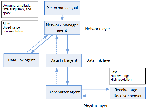
Figure 1. A hierarchical weakly coupled network. Only one link direction is shown in the physical layer.
The agents in the physical layer are adaptive transmitters and receivers, forming a communication link. Transmitters use sensor information received from the corresponding receiver sensors. A transmitter may change the direction (through beamforming), timing, frequency, and sometimes even the carrier phase of the transmission. Below each transmitter, an agent in the adaptive receiver controls the frame, symbol, and carrier phase synchronization locally. The transmission is bidirectional, and thus alongside each transmitter, there is a receiver and vice versa. The two directions are separated by different frequencies or time slots, defined by the data link agent, which more generally controls the use of the physical channel shared between several users. For brevity, we focus on one link direction only.
Hierarchical control decreases the complexity of a system with widely differing speed requirements. Without any hierarchy, the whole system should work at the highest speed. This would be inefficient as, for example, power consumption (in W or J/s) is directly proportional to the computing speed in operations per second (OP/s) and the energy efficiency of each operation (in J/OP).
Speeds at neighboring hierarchy levels can differ by orders of magnitude. In the network layer, the changes occur in 1-10 s intervals, in the data link layer in 1-10 ms intervals corresponding with the subframe and frame length, and in the physical layer in 0.1-1 s intervals when the bandwidth is 1-10 MHz. In the actual physical implementation, the minimum clock intervals are in the order of 1 ns when the maximum clock rates are 3-4 GHz.
The network consists of rational agents that sense and control the state of the network. Rationality means that the agent is able to reach its goals efficiently with a minimum amount of basic resources even in uncertain environments [2], [15]. According to the present theories in psychology, rationality is a more general and higher-level concept than intelligence. The agents in the highest hierarchy levels are complex and slow, while those in the lowest levels are simple and fast.
The range is broad, and the resolution low in the highest hierarchy levels, whereas the range is narrow, and the resolution high in the lowest hierarchy levels. The range and resolution are measured in amplitude, time, frequency, and spatial domains. For example, the range is the whole network in the network layer but a single link in the data link layer. In the physical layer, the range is related to a single physical parameter such as timing or carrier frequency. Therefore, the network layer has an overview of the situation and can better control the whole network for self-organization.
3. Stability is the most important requirement
Stability is the most important requirement for any system [1] as an unstable system is useless. Since self-organization is based on feedback loops in the form of rational agents, stability is a major problem to be solved. Stability depends on the properties of the feedback loops. First, only negative feedback loops are stable. Second, the speed of each loop must be much slower than the loop delay, and the loops in the hierarchy must have sufficient time-scale separation. Third, parallel loops must be uncoupled or mutually weakly coupled. The second and third properties are illustrated in Fig. 2, where each agent realizes a feedback loop.
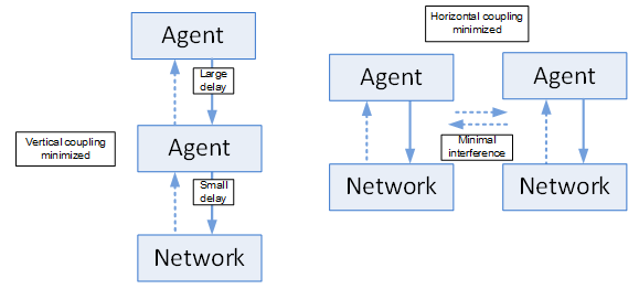
Figure 2. Stability of two feedback loops related to delays (left) and interference (right). The methods are called time-scale separation of hierarchy levels and interference avoidance between users, respectively.
The feedback may be negative or positive, but only negative feedback is known to be stable. For example, exponential growth is clear evidence of instability. Any exponential development will eventually stop because of fundamental limits and finite resources. For example, an amplitude range is always upper limited by saturation and lower limited by noise, thus forming limits to the resolution. If used, positive feedback must be located inside a negative feedback loop to stabilize the whole loop.
Feedback loops with the smallest possible delays and weakest possible mutual couplings have the best stability and highest convergence rate. This is the core idea in a weakly coupled network. As a communication network is spatially distributed, the delay may be significant when the distances between the components of a feedback loop (sensors, a decision block, and actuators) are long. A large delay may change negative feedback to unstable positive feedback. The delay can be shortened by placing all components of a feedback loop at the same location, either in a user equipment or in an edge server near the user. When this is not possible, feedback loops with long delays can be placed at higher hierarchy levels. These levels can operate slow enough because the feedback loops at the faster, lower hierarchy levels operate nearly autonomously. Slowness is a form of weak coupling. This is called time-scale separation of hierarchy levels [8].
In a wireless link, adaptive loops in the transmitter and receiver may be coupled and start to track each other, leading to instability. Here, the coupling can be decreased by placing the transmitter with its larger delay at a higher and slower hierarchy level than the receiver with its smaller delay. The delay in the transmitter is larger because of the physical distance to the receiver sensor (Fig. 1).
In the physical layer, the radio waves that tend to propagate in all directions may cause interference, hence increasing coupling between links. Transmitter power control loops provide an example of the effects of this coupling. If many users share a frequency band, the interference may cause a cocktail party effect: all transmitters tend to use the maximum power, resulting in poor performance. Coupling can be decreased, i.e., interference avoided between users, by using orthogonal signals in the physical layer. For example, time-division multiple-access is an interference avoidance method [10].
4. Scalability comes next
Scalability is also an important system requirement in SONs. The conventional degrees of centralization include centralized, decentralized, and distributed systems [2]. In communications networks, a decentralized system corresponds to a set of independent network nodes before actual networking. A centralized system is a tightly coupled system where the lower-level agents are forced to cooperate with each other. When the size of the system increases, the information needed to control the system grows exponentially. Also, the decision delays may be large, and hence stability problems are possible unless some hierarchy is used.
On the other hand, a decentralized system has no hierarchy, and the agents are autonomous and compete with each other. They optimize themselves, but the whole is not optimized because of their bounded rationality: individual agents usually do not make decisions that add up to the good of the whole. If evolution is possible, this may or may not slowly lead to optimization. In practice, centralized systems drift towards partial decentralization and decentralized systems towards partial cooperation.
A compromise between centralized and decentralized systems is a distributed system. There is no hierarchy, but the agents exchange information, at least with their closest neighbors. In this way, they slowly get an overview of the situation of the whole network. Distributed systems have many beneficial properties, such as scalability. However, decentralized and distributed systems use competition, and such systems may not be optimal.
We need another compromise between centralized and decentralized systems. The compromise is a combination of centrally controlled and distributed networks called hybrid control [5], [6]. In such a weakly coupled hierarchical system, the central agent is weak, and the lower-level agents act almost autonomously. This architecture introduces flexibility since it supports all degrees of centralization, from centrally controlled at one extreme to decentralized at another extreme, and anything in between (e.g., distributed), depending on the strength of the coupling. In conclusion, weakly coupled systems can obtain scalability.
5. Efficiency, reliability, and agility
Weakly coupled hierarchical networks have additional favorable properties, including efficiency, reliability, and agility [1]. The SONs suggested in this paper have these properties as they are weakly coupled. Biological systems are a product of the evolution of billions of years. They are weakly coupled and known to be highly efficient. Weakly coupled systems are reliable since errors do not propagate [14]. Reliability is also dependent on fault tolerance and robustness. These two properties are attained using feedback control, redundancy, structural stability, and modularity.
Optimal systems are efficient but not necessarily robust because they do not use redundancy. Thus, weakly coupled systems should also be redundant, for example, in the form of alternate routes from the source to the destination. As another example, if a network manager is destroyed, a weakly coupled network is still able to work if a substitute is available in a different geographical location. Weakly coupled systems are agile [4], which means that they can adapt to fast changes in the environment. For example, evolution would not have had enough time to develop in biology unless a weakly coupled hierarchical and modular system had been used.
6. Conclusion
We have proposed weakly coupled systems in the form of hybrid SONs as the basis for the architecture of future networks. A hybrid SON combines the ideas of distributed and weak centralized control. Such networks have many favorable properties, including stability, scalability, efficiency, reliability, and agility. Stability is a core requirement since otherwise, a network is useless. Stability may be compromised if one is not careful since the new intelligent network architectures include feedback loops consisting of sensors, decision blocks with some externally given goals, and actuators that change the state of the network. Large delays may change a negative feedback loop to a positive feedback loop. Furthermore, the loops may interact with each other, especially at the lowest level, because of interference. These problems can be avoided by decoupling the feedback loops from each other using time-scale separation of hierarchy levels and interference avoidance between users. All feedback loops at different hierarchy levels and at the same hierarchy level must be decoupled. This is our main contribution in this paper. Such weakly coupled systems have a long history since the 1960s, and therefore many of their properties have been tested in different disciplines. An important research problem for the future is the selection of the performance goals and related constraints to jointly optimize bit rates, reliability, delays, and energy efficiency.
Acknowledgment
This work was supported in part by the EU H2020 project DEDICAT 6G under Grant no. 101016499 and in part by the Academy of Finland through the 6G Flagship project under Grant no. 318927. The contents of this publication are the sole responsibility of the authors and do not in any way reflect the views of the EU. Discussions with Abdelaali Chaoub, Ranganai Chaparadza, and Jyrki Huusko are gratefully acknowledged.
References
[1] A. Mämmelä and J. Riekki, “Subsidiarity and weak coupling in wireless networks,” in Proc. EuCNC’21.
[2] J. Riekki and A. Mämmelä, “Research and education towards smart and sustainable world,” IEEE Access, vol. 9, pp. 53156-53177, 2021.
[3] S. Russell and P. Norvig, Artificial Intelligence: A Modern Approach, 3rd ed. Upper Saddle River, NJ: Prentice-Hall, 2010.
[4] O. G. Aliu, A. Imran, M. A. Imran, and B. Evans, “A survey of self-organisation in future cellular networks,” IEEE Commun. Surveys Tuts., vol. 15, no. 1, pp. 336-361, 1st Quart., 2013.
[5] H. Fourati, R. Maaloul, L. Chaari, and M. Jmaiel, “Comprehensive survey on self-organizing cellular network approaches applied to 5G networks,” Computer Networks, vol. 199, pp. 1-24, 9 November 2021, Art. no. 108435.
[6] ETSI TS 103 195-2 V1.1.1, “Autonomic network engineering for the self-managing Future Internet (AFI); Generic Autonomic Network Architecture; Part 2: An architectural reference model for autonomic networking, cognitive networking and self-management,” May 2018.
[7] “O-RAN operations and maintenance architecture,” O-RAN Alliance, Alfter, Germany, Technical Specification O-RAN.WG1.O-RAN-Architecture-Description-v05.00, July 2021.
[8] I. F. Akyildiz and X. Wang, “Cross-layer design in wireless mesh networks,” IEEE Transactions on Vehicular Technology, vol. 57, no. 2, pp. 1061-1076, March 2008.
[9] A. Bayazeed, K. Khorzom, and M. Aljnidi, “A survey of self-coordination in self-organizing network,” Computer Networks, vol. 196, pp. 1–32, 4 September 2021, Art. no. 108222.
[10] G. J. Pottie, “System design choices in personal communications,” IEEE Personal Communications, vol. 2, no. 5, pp. 50 - 67, Oct. 1995.
[11] M. E. J. Newman, Networks: An Introduction, 2nd ed. New York: Oxford University Press, 2018.
[12] A. Helmy, “Small worlds in wireless networks,” IEEE Communications Letters, vol. 7, no. 10, pp. 490-492, October 2003.
[13] B. A. A. Nunes, M. Mendonca, X.-N. Nguyen, K. Obraczka, and T. Turletti, “A survey of software-defined networking: Past, present, and future of programmable networks,” IEEE Commun. Surveys Tuts., vol. 16, no. 3, pp. 1617–1634, 3rd Quart., 2014.
[14] C. Pautasso and E. Wilde, “Why is the web loosely coupled? A multi-faceted metric for service design,” in Proc. WWW’09.
[15] K. E. Stanovic, R. E. West, and M. E. Toplak, The Rationality Quotient: Toward a Test of Rational Thinking. Cambridge, MA: MIT Press, 2016.
Biographies Aarne Mämmelä received the degree of D.Sc. (Tech.) (with honors) from the University of Oulu in 1996. He was with the University of Oulu from 1982 to 1993. In 1993 he joined the VTT Technical Research Centre of Finland in Oulu. Since 1996 he has been a Research Professor of wireless communications. He visited the University of Kaiserslautern in Germany in 1990-1991 and the University of Canterbury in New Zealand in 1996-1997. He has been an advisor to 10 doctoral students and published over 40 journal papers and over 100 conference papers.
 Jukka Riekki received the D.Sc. (Tech.) degree from the University of Oulu, Finland, in 1999. Since 2001, he has been a professor of software architectures for embedded systems at the University of Oulu and since 2014, the Dean of the Faculty of Information Technology and Electrical Engineering. He visited Intelligent Systems Division, Electrotechnical Laboratory, Tsukuba, Japan, in 1994–1996. He has been an advisor of 10 doctoral theses. He has published 45 journal papers, six book chapters, and over 180 conference papers.
Quantum-inspired Processing for System Optimization in Emerging Networks
Dilip Krishnaswamy (This email address is being protected from spambots. You need JavaScript enabled to view it.)
Abstract
This paper explores quantum-inspired techniques for resource management and optimization of emerging wireless networks. As wireless networks continue to evolve into 6G and beyond, the deployment of networks will be increasingly heterogeneous comprising of base-stations or access points or distributed units serving users in different spectra utilizing different technologies, with self-organizing features enabled. A Quasi-quantum graph colouring algorithm can be considered using virtual cell identifiers to coordinate across access nodes and to enable such networks to be optimized. Dynamic energy savings can be performed in a quadratic unconstrained binary optimization framework. Dynamic load balancing is suggested using an entangled quantum state variable across access nodes, to represent a distributed network availability state. In general, a distributed probabilistic quantum state vector can be utilized to enable quantum-inspired resource optimization in emerging networks for different network optimization problems.
Introduction
As research in the 6G domain advances, the telecommunications industry is entering an inflection point to pursue interesting challenges to work on newer network architecture paradigms and to utilize new and emerging technologies. The increased heterogeneity of technologies for accessing networks such as based on 4G or 5G-NR or WiFi6 or 5G-NR-Unlicensed or B5G (Beyond 5G) or 6G [1][2][3][4], variability in large and small cells, options for centralized versus disaggregated RAN (Radio Access Network) solutions, and programmable infrastructure, ensuring different levels of quality of service for different network slices, distributed and partitioned private and public 5G and edge networks, smart utilization of local and distributed intelligence in networks, and enabling new applications and services, all provide interesting challenges for system optimization in such networks. Such emerging systems will process information in an increasingly distributed and probabilistic manner. This paper provides a framework to explore quantum-based processing to help with system optimization in such emerging networks.
RAN System Optimization
To optimize resources in the RAN domain, the O-RAN (Open RAN) architecture [5] includes capabilities for a Non-Real-Time RAN Intelligent Controller (NonRT-RIC) in a Service and Management Orchestration (SMO) layer associated with the RAN to assist with delay-tolerant optimizations for the RAN. In addition, a Near-Real-Time RAN Intelligent Controller (NearRT-RIC) is placed closer to the RAN to assist with delay-sensitive optimizations for the RAN. These RICs interact with Central Units (CUs), or Distributed Units (DUs) or Radio Units (RUs) in the network. The RU provides support for antennas, radio communications (Tx/Rx), and the lower physical layer. The DU provides support for lower layers of the overall RAN protocol stack such as the upper physical layer, the MAC layer and the RLC layer. The CU provides support for control and upper layers of the RAN protocol stack such as the RRC, PDCP, and the SDAP layers. System information metrics/parameters from the CUs, DUs, and RUs are monitored and aggregated at the RICs and stored in a system information model (typically a yang model) that can vary dynamically. Changes to such a system model are continuously monitored. In addition, changes to specific metrics that are related to a specific optimization function can be computed and monitored, and these changes can be used to trigger the execution of such optimization functions. These optimization functions can relate to Self-Organizing Network (SON) [6][7][8] functions for the RAN and into other network segments which have been progressively proposed in cellular standards including
- Automatic Neighbor Relations (ANR)
- Automatic Physical Cell ID (PCI) assignment
- Mobility Robustness/Handover optimization (MRO)
- Load Balancing Optimization (LBO)
- Coverage & Capacity Optimization (CCO)
- Random Access Channel (RACH) Optimization
- InterCell Interference Coordination (ICIC)
- Enhanced InterCell Interference Coordination (eICIC)
- Minimization of Drive Testing (MDT)
- Energy Savings (ES)
- Handover Optimization (HO)
- Cell Outage Detection and Compensation
- Self-healing Functions
- Coordination between various SON Functions
Typically, most SON functions are processed in a centralized manner. A more flexible realization for Hybrid SON is also possible that utilizes both distributed SON and centralized SON, allowing the distributed optimization components to focus on local optimization, whereas the centralized SON optimizes across the distributed components, providing useful feedback to the distributed components for improved local optimization.
In general, a Heterogeneous RIC (Het-RIC) [18] can be explored, where such a Het-RIC manages other radio access technologies and systems as well such as WiFi access points (APs), 4G eNodeBs, 5G gNodeBs, or 6G-cells, in addition to disaggregated components such as CUs, DUs, and RUs.
Quantum-Inspired Optimization
Quantum-based systems support the notion of a probabilistic state vector across different state dimensions in a system [9][10][11][12][13][18][20]. For emerging distributed processing systems in networks, quantum-state vectors can be used to represent the overall distributed state information in the system. The state of the system can then evolve probabilistically based on unitary transforms associated with quantum state variables. The amplitudes associated with quantum states can be progressively refined such that a collapse of the state can result in an optimal solution to a system optimization problem. Such an approach can be utilized for different types of system optimization problems such as PCI optimization in heterogeneous and disaggregated networks, distributed energy management in networks, load balancing in heterogeneous networks, or network-access coordination across access nodes and devices. A Quantum State Variable (QSV) can be associated with one or more physical qubits, or one or more virtual qubits. Quasi-quantum processing can be done using virtual qubits or quantum state variables (QSVs) in a classical computer. Alternatively, quantum processing can be done using physical qubits in a quantum computer. Hybrid implementations are also possible where some processing is done in a quantum computer assisted by processing performed on a classical computer. In the case of a physical qubit, the state of the qubit will not be fixed and will remain in a state of superposition, until it is measured. Prior to measurement, a physical qubit is in a state of superposition across possible states. When the state of a physical qubit is measured, then the state of the qubit will collapse to one of the possible states.
Dynamic PCI Optimization
Traditionally, PCI optimization is formulated as an NP-complete graph coloring-based optimization problem with each cell as a node in the graph, with edges in the graph between neighboring cells [14][15][16][17][18]. To be relevant to emerging heterogeneous networks operating in virtualized infrastructure, one can create a virtualPCI (vPCI) number [18] that is managed in such infrastructure and associated with the cells, such that an extended range beyond [0-1007] is possible in the network. Cell IDs associated with non-4G or non-5G-NR cells or newer-6G cells could take on values beyond the available range for 4G/5G deployments. The color (equivalently the vPCI value) of a node i can take on one of any of 1≤k ≤ K colors in a network graph. The system optimization results in the determination of the value for the color of each of the cells such that PCI collision or confusion is avoided in the network. Dynamic optimization can be done locally utilizing only a small subset of IDs allocated to a network graph representing nodes in a local geographical region to avoid conflicts across regions. A collision occurs when two nodes have the same color or vPCI value in the same network graph. A confusion occurs when two neighbors of the same node have the same color or vPCI value in the network. From the perspective of a quantum-inspired framework, it would be useful to study this problem as a graph with nodes whose colors (PCI values) are determined based on a quantum-state variable (QSVs) associated with that node, where different states correspond to different possible color assignments to nodes. The state probabilities associated with the QSVs for the nodes in the graph can be refined when there are edge conflicts between nodes that have the same color. For this purpose, one can define a single Quantum State Variable (QSV)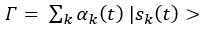 ………………………….…..(1)
with K states (or colors) that could be associated with a given cell, such that a collapse of the QSV to one of the K states results in the determination of the color (or vPCI value) for that cell [18]. The state of a QSV is given by a superposition of K states from the set {|s_1 (t)>, |s_2 (t)>, ……., |s_K (t)>}, such that |α_k (t) |^2 is the probability associated with state |s_K (t)>. The collisions in the graph are determined based on color conflicts given an adjacency matrix A for the network graph. Figure 1 shows the reduction in PCI conflicts as the optimization is iteratively performed. As the number of available colors was increased, the system required fewer iterations to converge as expected to eliminate conflicts, due to the greater degrees of freedom afforded by a larger number of available colors.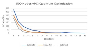
Figure 1: Quantum-inspired vPCI Optimization [18]
To avoid confusions in the network, a similar optimization is performed on the square of the adjacency graph A2 to determine two step-walks in the graph. This allows neighbors of a given node in a network graph with adjacency matrix A, to become neighbors of each other in a network graph with adjacency matrix A2. In effect, the detection of confusion in the original network graph with adjacency matrix A becomes equivalent to the detection of collision in the new network graph with adjacency matrix A2.
Dynamic Energy Savings
When the utilization of the network falls below a threshold such that the available capacity is large in different cells in the network, and if the corresponding access nodes (gNodeBs, eNodeBs, or WiFi-APs, or Distributed Units (DUs) associated with gNodeBs or 6G-cells) are jointly covering the same geographical region, then a D-Wave based quantum optimization framework can be relevant to determine which nodes to keep active, and which to turn off for energy savings. A D-Wave system [19] contains a Quantum Processing Unit (QPU) operated at a temperature close to absolute zero, where the system is designed to naturally execute annealing algorithms that attempt to minimize system energy. A D-Wave QUBO (Quadratic Unconstrained Binary Optimization) problem is defined with the goal of minimizing an energy function E (also known as the Hamiltonian for the system) given by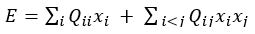 …………...…………..(2)
The terms x_i take on values 1 or 0 to indicate whether an access node is on or off in the system. This is based on the Ising Model where the variables represent "spin up" or "spin down" states. Self-coupling coefficients Q_ii can be used to provide an opportunity for a node to provide service with the value depending on the size of the coverage area provided by the node in the region. The more negative value of a self-coupling coefficient, the more likely that the node represented by the coefficient is turned on in the network. The cross-coupling coefficients Q_ij represent the degree of correlation between nodes in the network. Such a self-coupling coefficient can be used to provide an opportunity for a node to provide service where the value can depend on the size of the coverage area provided by the node in the region, or the cost of service from the node in the region. The coupling between two nodes can represent either a positive or negative correlation. A negative value of a cross-coupling coefficient increases the likelihood of two nodes jointly serving a network thus lowering energy in the system, whereas a positive value of the cross-coupling coefficients has the opposite effect, increasing system energy and reducing the likelihood of two nodes jointly serving the network. A positive value of the cross-coupling coefficient can be used for example, if two nodes have a common area that they are covering, so that the magnitude of the coupling reflects the degree of overlap. Similarly, a negative value could be used if two nodes cover different areas, with a higher degree of negative coupling if the nodes are highly separated from each other. If the cross-coupling coefficient Q_ij between two nodes has a positive value, and yet, if that cost is lower in magnitude relative to the magnitude of the sum of the negative self-coupling costs Q_ii and Q_jj for the two nodes i and j respectively, then the overall cost/energy to jointly utilize both access nodes is negative. Alternatively, if a positive cross-coupling coefficient is higher in magnitude relative to the negative self-coupling costs for the nodes, then the joint utilization of the nodes results in a higher energy system. In general, the costs associated with utilization of all access nodes needs to be jointly considered, so that a joint optimization across all nodes is needed for an overall determination of which access nodes can be kept on at any given time. This technique was implemented in the D-Wave QUBO simulator. For example, when the self-coupling values and cross-coupling values as listed in Table 1 are utilized, and the cross-coupling terms are utilized only once for any pair of nodes as shown in equation 2, then the system settles down to a low energy state of -14 units with an allocation of 10011 across the nodes, enabling nodes 1 and 2 to go to sleep, while keeping nodes 0, 3 and 4 active in the system. Such a formulation can thus be used for energy optimization across a network of base-stations or access points, by utilizing a quantum-system representing the system state to evolve, anneal, and settle down to a low energy state that minimizes system energy.
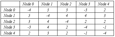
Table 1: Self-coupling and cross-coupling coefficients between access nodes for joint energy optimization in a network.
Dynamic Load Balancing Optimization
Consider N access nodes in a wireless network collaborating to provide access to different users in a network in a common geographical area. These nodes could be operating in different frequency bands in the same geographical region so that the load on access nodes is utilized to determine which node provides access to a particular user in that region. In that regard, one can create a QSV that is entangled across different access nodes in the network, where each access node has a state | si(t)> where i = 1, 2,…., N. Let us assume that we are seeking an access node i that can provide network access to a new user. In this regard, we can create a quantum state ψi(t) which is a superposition of the states |si(t)> for these N access nodes, where the state |si(t)> represents node i serving a new user at time t, given by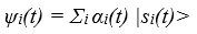 …………………….……………(3)
Here, the state probability is given by the square of the amplitude αi(t) representing the likelihood of access node i serving a new user at time t. In the simple case, when all states are equally likely with probability 1/N, then the amplitudes αi(t) have values 1/√N. In general, these probabilities across the access nodes would vary dynamically depending on the available capacity and current load at each access node. We seek an access node that has a lighter load relative to other nodes such that a node with a lighter load has a higher amplitude in the QSV, so that it would have a higher likelihood of being selected to serve a new user in the network. Since the nodes share an entangled QSV, a collapse of the QSV helps in determining which node provides access across all the nodes. To maintain an updated version of the state, each access node i would have to periodically exchange its current load Li(t) and their total capacity Ci(t), with other nodes in the network, to enable its dynamic available capacity, Ai (t) = Ci(t) – Li(t) to be computed by other nodes. Alternatively, nodes could merely exchange their dynamic available capacity Ai (t) periodically. This allows the state probabilities p_i(t) = A_i(t) / (Sigma_j A_j(t) ) to be computed so that they are proportional to the dynamic available capacities of each of the nodes i, to then determine the state amplitudes α_i (t)= √(p_i (t)) for the distributed probabilistic quantum state vector across the nodes. Such processing can be directly performed by a central neutral entity such as a Het-RIC associated with a heterogeneous Central Unit (Het-CU) that coordinates network access across the access nodes and performs a state collapse of an entangled QSV across the nodes. A quantum blockchain network [20] across these nodes can also be utilized, if desired, for shared distributed processing, to exchange and share metrics with a smart contract executed across nodes for shared decision-making. It can be seen from Figure 2 that the load gets progressively better-balanced across the network as new users join the network by utilizing the collapse of a QSV across the nodes to admit such new users. 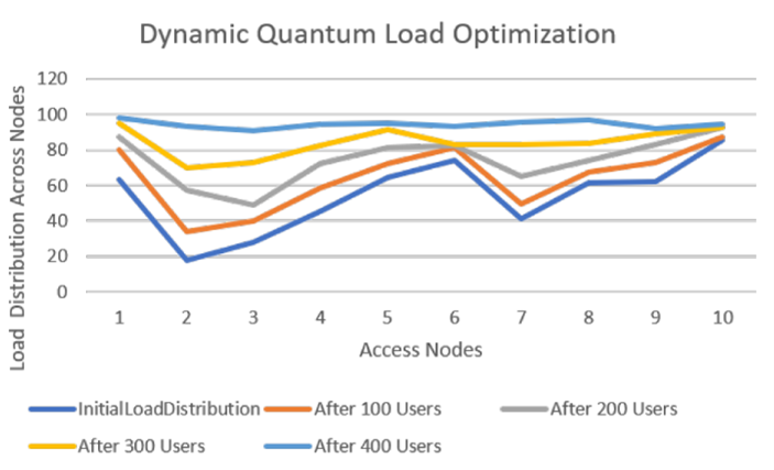
Figure 2: Dynamic Quantum Load Optimization across N access nodes (N = 10) serving mobile users in a wireless network
Each curve shows the distribution of load across the nodes after each iteration starting with the lowermost initial load distribution curve in the graph. As new users join the network, the load across the network is progressively distributed more equitably across the access nodes in the network.
Summary and Future Possibilities
To summarize, this paper has suggested quantum-inspired algorithms that utilize probabilistic state information in quantum state variables (QSVs), or entangled QSVs to assist with resource optimization in emerging wireless networks. Of late, RAN Intelligent Controllers are being explored in emerging programmable networks that operate across multiple cells and across available licensed/unlicensed wireless networks, that interact with centralized units (CUs) and/or distributed units (DUs) and/or WiFi Access points, where the suggested algorithms could be deployed. Resource management problems such as PCI optimization, energy optimization, and load balancing optimization were explored in this work. It is possible that other SON functions and system optimization problems could be explored in a similar manner utilizing the notion of a distributed probabilistic state that can be encapsulated in a quantum state variable.
References
[1] C. Johnson, “5G New Radio in Bullets,” 1st edition, 2019.
[2] IEEE 802.11 standards, https://www.ieee802.org/11/ [Online: Accessed January 15, 2022].
[3] IEEE Future Networks, “IEEE 5G and Beyond Technology Roadmap,” https://futurenetworks.ieee.org/images/files/pdf/ieee-5g-roadmap-white-paper.pdf [Online: Accessed January 15, 2022].
[4] 5G Infra Assoc, “European Vision for the 6G Network Ecosystem,”
https://5g-ppp.eu/wp-content/uploads/2021/06/WhitePaper-6G-Europe.pdf [Online: Accessed January 15, 2022].
[5] O-RAN Alliance, https://www.o-ran.org/ [Online: Accessed January 15, 2022].
[6] A. Chaub et al, “Self-Organizing Networks in the 6G Era: State of the Art, Opportunities, Challenges, and Future Trends,” https://arxiv.org/abs/2112.09769, [Online: Accessed January 15, 2022].
[7] N. Marchetti et al, “Self-Organizing Networks: State-of-the-art, challenges and perspectives,” Proc. IEEE Int. Conf. Commun. Workshops (ICC), June 2010.
[8] J. Moysen and L. Giupponi, “From 4G to 5G: Self-organized Network Management meets Machine Learning,” Computer Communications, Vol. 129, pp. 248-268. Sep 2018.
[9] R. Eisberg, and R. Resnick, “Quantum Physics of Atoms, Molecules,
Solids, Nuclei, and Particles,” 2nd edition, 2003, Wiley Publishing.
[10] B. H. Bransden and C. J. Jochain, “Quantum Mechanics,” 2nd edition, 2000, Pearson Education.
[11] M. A. Neilsen and I. L. Chuang, “Quantum Computation and Quantum Information,” 10th edition, Pearson Education, 2016.
[12] National Academies of Sciences, Engineering, and Medicine 2019, “Quantum Computing: Progress and Prospects,” Washington, DC: The
National Academies Press, https://doi.org/10.17226/25196. [Online: Accessed January 15, 2022].
[13] S. Imre, “Quantum Communications: Explained for Communication Engineers,” IEEE Communications Magazine, August 2013.
[14] M. Amirijoo et al, “Neighbor Cell Relation List and Physical Cell
Identity Self-Organization in LTE,” Proc. IEEE Int. Conf. Commun.
Workshops (ICC), May 2008, pp. 37–41.
[15] R. Acedo-Hernandez et al, “A PCI planning algorithm for jointly
reducing reference signal collisions in LTE uplink and downlink,”
Computer Networks, vol. 119, pp. 112–123, Jun. 2017.
[16] S. Nyberg, “Physical Celll ID Allocation in Cellular Networks,” Technical Report, Master’s Thesis, Linkoping University, 2016.
[17] J. Gui, Z, Jiang, S. Gao, “PCI Planning based on Binary Quadratic
Programming in LTE/LTE-A Networks,”, IEEE Access, vol 7, pp. 203-
214, 2019.
[18] D. Krishnaswamy, “Quasi-Quantum PCI Optimization in 5G Networks,” IEEE Vehicular Technology Conference, Spring 2021.
[19] D-Wave Systems, https://www.dwavesys.com/ [Online: Accessed January 15, 2022],
[20] D. Krishnaswamy, “Quantum Blockchain Networks,” BlockNet Workshop at ACM Mobihoc 2020.
Bio Dilip Krishnaswamy received a PhD in electrical engineering from the University of Illinois at Urbana-Champaign. He is an inventor on 60+ granted US patents, and has co-authored 70+ research publications. He has worked at Intel Corp., Qualcomm Research, IBM Research, and Jio Platforms, and he is currently a senior principal architect at Sterlite Access Solutions.
How does SVC enable Distributed Caching in MEC?
Suvadip Batabyal, Department of Computer Science and Information Systems, BITS Pilani Hyderabad Campus, India.
1. Abstract
With an ever-increasing demand for the delivery of internet video services, the service providers are facing a huge challenge to deliver ultra-HD (2k/4k) video at sub-second latency. The multi-access edge computing (MEC) platform helps achieve this objective by caching popular content at the edge of a cellular network. This reduces the delivery latency and the load, and the cost of the backhaul links. However, MEC platforms are afflicted by constrained resources in terms of storage and processing capabilities, and centralized caching of contents may nullify the advantage of reduced latency by lowering the offloading probability. Distributed caching at the edge improves the offloading likelihood and dynamically adjusts the load distribution among the MEC servers. In this article, we propose an architecture for the deployment of MEC platforms by exploiting the characteristics of a scalable video encoding technique. The content providers use layered video coding techniques, such as scalable video coding (SVC), to adjust to the network dynamics by dynamically dropping packets to reduce latency. We show how an SVC video easily lends itself to distributed caching at the edge. Then we investigate the latency-storage trade-off by storing the video layers at different parts of the access networks.
2. Introduction
As per the Cisco annual report, nearly two-thirds of the global population will have access to the internet by 2023, with video services consuming the majority of the bandwidth provided by mobile network operators and internet service providers. Globally, devices and connections are growing faster (10% CAGR) than both population (1.0% CAGR) and the internet users (6% CAGR). This increase is putting a tremendous challenge on the service providers to meet the consumer’s requirement for bandwidth, especially for the delivery of ultra-HD or 2k and 4K videos. Additionally, there is an increasing demand for videos with a bit rate (15-18Mbps for 4K videos), augmenting the challenge of best service delivery. With this fact, the mobile network operators (MNOs) and service providers are (i) deploying ultra-dense networks for energy-efficient coverage of urban landscape, (ii) deploying multi-access edge computing (MEC) platforms for low-latency delivery of multimedia contents and reducing the transport cost of the backhaul networks.
2.1 Ultra-dense Networks
Ultra-dense networks (UDNs) [1] are realized through the deployment of small cells, which are access points with small transmission power (and hence coverage). These access points cater to the service requirement of a significantly small percentage of the population. DNS facilitates the reuse of frequency spectrum energy-efficient and improves link quality (bits/hertz/unit area). The small cell access points may be a fully functional base station (picocell or femtocell) or a remote radio head (RRH). The fully functioning BS can perform all the functions of a macrocell with lower power in a smaller coverage area. The small cell BSs (SBSs) may be connected to the macrocell BS (MBS) using wireless or wired backhaul technology. Although wired backhaul can provide a higher data rate, due to the growing number of SBS, wireless backhaul is more cost-effective and scalable.
2.2. Multi-access Edge Computing
MEC is a natural development in the evolution of mobile base stations and the convergence of IT and telecommunications networking. Multi-access Edge Computing will enable new vertical business segments and services for consumers and enterprise customers. It allows the software applications to efficiently tap into local content and obtain real-time information about local-access network conditions. By deploying various services and caching contents at the network edge, mobile core networks are alleviated of further congestion and can efficiently serve local purposes. MEC uses cases include computation offloading, distributed caching and content delivery, enhanced web performance, etc.
The MEC architecture [2] typically consists of a host-level and a system-level manager. The MEC system-level management includes the multi-access edge orchestrator (MEO) as its core component, an overview of the complete MEC system. The MEO has visibility over the resources and capabilities of the entire mobile edge network, including a catalog of available applications.
3. Deployment Architecture
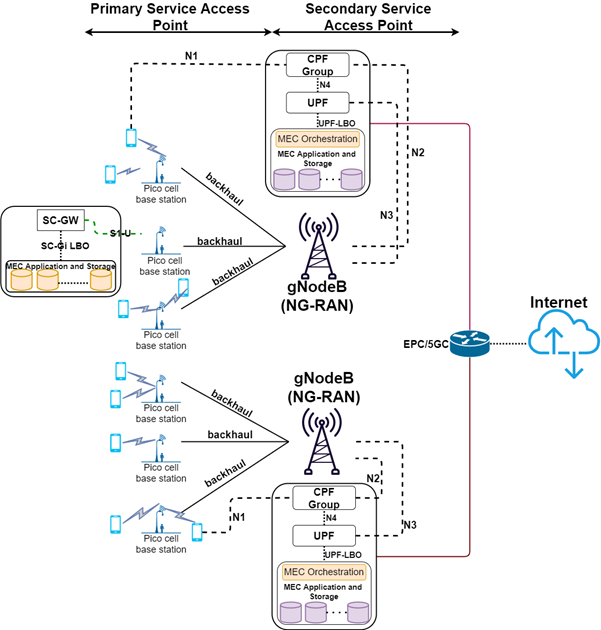
Figure 1: Architecture for SVC-based distributed caching.
Figure 1 shows the proposed deployment architecture. The architecture is divided into two slices (i) primary service access points (P-SAPs) and (ii) secondary service access points (S-SAPs). The P-SAPs consist of the small-cell base stations along with the MEC platform. The S-SAPs consist of the macro-cell base stations and the MEC platform. The user equipment (UEs) are typically attached to the P-SAPs and get serviced by them. The UE gets attached to the S-SAPs only under zero coverage by the P-SAPs. The P-SAPs consist of two main modules, the user plane functionality (UPF) and the MEC platform. The S-SAPs consist of three main modules: the user plane functionality (UPF), the control plane functionality (CPF), and the MEC platform. The UPF in P-SAPs consists of a small cell serving gateway (SC-GW) [3]. SC-GW is primarily responsible for routing traffic to and from the core network to the UEs. It can also take care of handover under mobility from one SBS to another. The SC-GW is attached to the MEC platform using an SC service gateway interface with local breakout (SC-Gi LBO). It may be mentioned here that both the SC-Gi LBO and the MEC application may be hosted as VNFs (virtual network functions) in the same MEC platform. In S-SAPs, the CPF consists of various functionalities such as network exposure functions (NEF), network resource function (NRF), authentication server function (ASF), etc. The UPF is connected to the CPF, bearing the service gateway, through the N4 interface. Like the P-SAP, the UPF is connected to the MEC platform using the S-GW LBO.
The MEC platform (in both P-SAPs and S-SAPs) primarily consists of two components: the MEC orchestrator (MEO) and MEC application and storage. The MEO is responsible for maintaining an overall view of the MEC system based on deployed MEC hosts, available resources, MEC services, topology, etc. The MEC application services may include computation offloading, content delivery, edge video caching, etc. The storage system stores the contents to be delivered to the UE in real-time during a service request.
We exploit the characteristics of the layered coding techniques for distributed caching[4][5] in the proposed architecture. A layered video coding technique, such as scalable video coding (SVC), consists of a base layer with multiple enhancement layers. The number of layers in a video (besides other factors) depends on the desirable video size (or downloadable segment size) for the application and the level of scalability required. The enhancement (or higher) layers are encoded on the base layer (or layer-0). Moreover, each higher layer is encoded to its previous layers. The reception of the stream’s base layer is mandatory to play the video without a stall or a skip, albeit at a lower quality, and also to decode the enhancement layers. With the reception of enhancement layers, the video quality keeps improving. We propose two schemes for caching any video on the MEC platform. Case 1: The base layer of a video is stored at the SBS MEC, and the enhancement layers are stored in MBS MEC. Case 2: The base layer is stored in the MBS MEC, and the enhancement layers are stored in SBS MEC. The above caching decision is decided by the MEO hosted at the secondary service access point and essentially in the gNodeB. The MEO has visibility over the resources and capabilities of the entire mobile edge network, including a catalog of available applications. The MEO (in the current context) decides whether to cache a particular video segment based on the available resources and system performance. This decision is taken based on the storage availability, access profile of the video, and other video characteristics. The SBS first handles requests for access to the video. If available, the user is serviced; this is also notified to the MEO. The MEO handles the requests and decides whether to forward the video to the SBS for storage. The MEO runs daemon processes to track system parameters based on such decisions. We analyze the latency and storage capacity trade-off for the above schemes and determine the factors that affect both schemes’ performance.
4. Trade-off Analysis
We perform a cache capacity to latency trade-off using an SVC video. The video has 20 GOPs where each GOP is of 2 seconds. The SVC is encoded at a constant bit rate of 16Mbps, typically the standard average bit rate for a 2K video with a frame rate of 30Hz. Each video has a base layer and four enhancement layers. The enhancement layers contribute to 20% of the GOP size, the remaining 80% being contributed by the base layer. Therefore, given the settings, the size of a GOP is 32Mb, out of which 25Mb (approximately) is the size of the base layer; and all the enhancement layers (taken together) make up 7Mb.
Next, we assume that the SBS can provide a data rate (depending upon different configurations) varying between 100Mbps to 1000Mbps (although practically, data rates above 500Mbps are still a vision). The MBS can provide a data rate ranging between 10Mbps to 100Mbps. We assume that an MBS has a storage capacity four times that of an SBS. A similar assumption and analysis can be found in [6]. It is to be mentioned here that there exists an asymptotic relation of storage size and download data rate between SBS and MBS. Therefore, any other experimental parameter that adheres to the asymptotic relation will not change the basic inferences.
4.1. Caching Rules
We assume two caching rules, viz.,
1. Rule-1: when the base layer of a video is stored in the SBS cache, and enhancement layers are stored in MBS. If the base layer of a video is found in SBS, then the enhancement layer will be found in MBS. However, the vice-versa is not valid. If the base layer is not found in SBS, then the enhancement layer may or may not be there in the MBS, depending upon the popularity of the video.
2. Rule-2: When a video's base layer is stored in MBS, enhancement layers are stored in SBS. If the base layer is found in MBS, the enhancement layer will be found in SBS and vice-versa.
Several cache replacement strategies have been proposed in this context [7]. We assume a popularity-based cache replacement strategy here.
4.2 Results
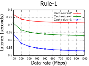
(a)
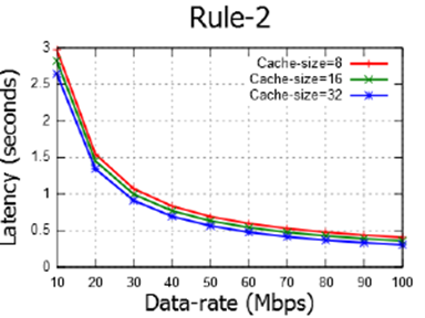
(b)
Figure 2: Graph of latency (seconds) against data-rate (Mbps) for (a) Rule-1 (b) Rule-2
Figures 2a and 2b show the latency against data rates for three different cache sizes under rule-1 and rule-2, respectively. It can be observed that:
1. Average latency under rule-1 is significantly smaller compared to rule-2. This is due to the higher data rate in SBS.
2. The rate of decrease in latency is higher under rule-2 than rule-1 as the data rate is improved. This is because of asymptotically higher data rates in SBS than MBS, even for smaller cache hit-ratio.
3. Latency is more negligible in MBS than SBS when the data rate is 100Mbps. This is because of the higher cache hit ratio in MBS.
4. Cache hit-ratio does not play a significant role under asymptotically smaller data rates, viz., in the case of rule-2. This is because of the bottleneck caused due to the lower transmission rate aided by the latency of the backhaul network.
5. Conclusion and Future Directions
We proposed an architecture for distributed caching of an SVC video and performed a latency-storage trade-off. It is envisaged that a higher storage capacity
at MEC incurs a higher cost and requires a higher power supply. Therefore, SBS can support only a small cache size compared to MBS. We find that SBS yields significantly improved latency under higher data rates. On the other hand, MBS can deliver similar latency under a higher hit ratio obtained by larger cache size. In the future, it would be interesting to investigate latency and cost trade-offs, where cost may be calculated as the weighted sum of storage capacity and bandwidth.
References
[1] M. Kamel, W. Hamouda and A. Youssef, “Ultra-Dense Networks: A Survey,” in IEEE Communications Surveys & Tutorials, vol. 18, no. 4, pp. 2522-2545, Fourthquarter 2016, doi: 10.1109/COMST.2016.2571730.
[2] https://www.etsi.org/deliver/etsi_gs/mec/001_099/003/02.01.01_ 60/gs_mec003v020101p.pdf
[3] A. Filali, A. Abouaomar, S. Cherkaoui, A. Kobbane and M. Guizani, “Multi- Access Edge Computing: A Survey,” in IEEE Access, vol. 8, pp. 197017- 197046, 2020.
[4] B. Jedari, G. Premsankar, G. Illahi, M. D. Francesco, A. Mehrabi and A. Yl ̈a-J ̈a ̈aski, “Video Caching, Analytics, and Delivery at the Wireless Edge: A Survey and Future Directions,” in IEEE Communications Surveys & Tutorials, vol. 23, no. 1, pp. 431-471, Firstquarter 2021, doi: 10.1109/COMST.2020.3035427.
[5] T. X. Tran and D. Pompili, “Adaptive Bitrate Video Caching and Processing in Mobile-Edge Computing Networks,” in IEEE Transactions on Mobile Computing, vol. 18, no. 9, pp. 1965-1978, 1 Sept. 2019, doi: 10.1109/TMC.2018.2871147.
[6] S. Zhang, N. Zhang, P. Yang, and X. Shen, “Cost-Effective Cache Deployment in Mobile Heterogeneous Networks,” in IEEE Transactions on Vehicular Technology, vol. 66, no. 12, pp. 11264-11276, Dec. 2017.
[7] X. Jiang, F. R. Yu, T. Song, and V. C. M. Leung, “A Survey on Multi-Access Edge Computing Applied to Video Streaming: Some Research Issues and Challenges,” in IEEE Communications Surveys & Tutorials, vol. 23, no. 2, pp. 871-903, Second quarter 2021.
Bio Suvadip Batabyal completed his Ph.D. from Jadavpur University, India in the year 2016. He is currently working as an Assistant Professor in the department of Computer Science and Information Systems at BITS Pilani Hyderabad Campus. He received the UGC-BSR fellowship during his Ph.D. He received the best Ph.D. forum paper award at IEEE ANTS 2017. He also received the TUBITAK visiting scientist fellowship in 2019 from the scientific and technological research council of Turkey. His current areas of research include QoE aware video streaming, edge computing, and device-to-device communication.
IEEE Tech Focus - April 2022
IEEE Future Networks Tech Focus
Issue 14, April 2022
In This Issue
- How does SVC enable Distributed Caching in MEC?
- Quantum-inspired Processing for System Optimization in Emerging Networks
- New network architectures will be weakly coupled
How does SVC enable Distributed Caching in MEC?
April 2022
Suvadip Batabyal, Department of Computer Science and Information Systems, BITS Pilani Hyderabad Campus, India.
With an ever-increasing demand for the delivery of internet video services, the service providers are facing a huge challenge to deliver ultra-HD (2k/4k) video at sub-second latency. The multi-access edge computing (MEC) platform helps achieve this objective by caching popular content at the edge of a cellular network. This reduces the delivery latency and the load, and the cost of the backhaul links. However, MEC platforms are afflicted by constrained resources in terms of storage and processing capabilities, and centralized caching of contents may nullify the advantage of reduced latency by lowering the offloading probability. Distributed caching at the edge improves the offloading likelihood and dynamically adjusts the load distribution among the MEC servers. In this article, we propose an architecture for the deployment of MEC platforms by exploiting the characteristics of a scalable video encoding technique. The content providers use layered video coding techniques, such as scalable video coding (SVC), to adjust to the network dynamics by dynamically dropping packets to reduce latency. We show how an SVC video easily lends itself to distributed caching at the edge. Then we investigate the latency-storage trade-off by storing the video layers at different parts of the access networks.
Quantum-inspired Processing for System Optimization in Emerging Networks
April 2022
Dilip Krishnaswamy (This email address is being protected from spambots. You need JavaScript enabled to view it.)
This paper explores quantum-inspired techniques for resource management and optimization of emerging wireless networks. As wireless networks continue to evolve into 6G and beyond, the deployment of networks will be increasingly heterogeneous comprising of base-stations or access points or distributed units serving users in different spectra utilizing different technologies, with self-organizing features enabled. A Quasi-quantum graph colouring algorithm can be considered using virtual cell identifiers to coordinate across access nodes and to enable such networks to be optimized. Dynamic energy savings can be performed in a quadratic unconstrained binary optimization framework. Dynamic load balancing is suggested using an entangled quantum state variable across access nodes, to represent a distributed network availability state. In general, a distributed probabilistic quantum state vector can be utilized to enable quantum-inspired resource optimization in emerging networks for different network optimization problems.
New network architectures will be weakly coupled
April 2022
Aarne Mämmelä, VTT Technical Research Centre of Finland, Finland
Jukka Riekki, Center for Ubiquitous Computing, University of Oulu, Finland
Future wireless network control architectures will be based on weakly coupled agents in the form of hybrid self-organizing networks that combine centralized and distributed control. Weakly coupled systems have been studied scientifically in many disciplines since the 1960s. Vertically and horizontally weakly coupled agents form a stable, scalable, and efficient hierarchical system. In communications, a central agent acts as a network manager with the purpose to guarantee fairness and constrain the use of basic resources such as energy, time, and bandwidth. The lowest level agents are transmitters and receivers that work almost autonomously due to weak vertical coupling. The system is based on time-scale separation of hierarchy levels: high-level agents act much more slowly than low-level agents. Horizontal coupling through interference between users is minimized by using orthogonal signals. This is called interference avoidance. All feedback loops at different hierarchy levels and at the same hierarchy level must be decoupled. This combination of vertical and horizontal decoupling of feedback control loops forms our main contribution in this paper.
IEEE Tech Focus - October 2021
IEEE Future Networks Tech Focus
Issue 13, October 2021
In This Issue
- Millimeter-wave Metantenna Technologies in 5G and Beyond
- Radio Propagation Modelling for Smart Environments in 5G/6G Networks
- Optical Transport for 5G Mobile Network: Challenges and Solutions
Millimeter-wave Metantenna Technologies in 5G and Beyond
October 2021
Zhi Ning Chen, Department of Electrical and Computer Engineering, National University of Singapore
The antenna is one of the most important technologies in all modern wireless networks. The deployment of new wireless systems always creates new technical challenges or opportunities for the development of antenna technologies from radiators to systems. The concepts of metamaterials have broken the boundaries of the conventional EM engineering. In particular, the applications of metasurfaces, a new design concept of two-dimensional EM structures, have offered the new opportunities to the innovative antenna technology. This article addresses the challenges and progress in the development of metamaterial/metasurface-based antennas, metantennas in short, in 5G millimeter-wave bands. Four design examples from 2 cases of flat lenses, a shared aperture to a dual-band metantennas demonstrate the applications of metantennas for 5G network. Of them one example of three-beam metalens antenna operating at 5G New Radio 2-GHz bands is also selected because the design method can be directly extended to the designs at millimeter-wave bands. The success in the applications of metantennas has shown the promising way for developing the antennas for new functionalities and new performance levels in 5G and beyond networks.
Radio Propagation Modelling for Smart Environments in 5G/6G Networks
October 2021
Jiliang Zhang, Department of Electronic and Electrical Engineering, The University of Sheffield, Sheffield, UK.
Jie Zhang, Department of Electronic and Electrical Engineering, the University of Sheffield, Sheffield, UK, and Ranplan Wireless Network Design Ltd., Cambridge, UK.
Over 80% of mobile traffic takes place in buildings. Building layouts and materials have a significant impact on radio propagation in indoor environments. While wireless link capacity is approaching the Shannon limit, optimizing building layouts and modifying material electromagnetic properties become a promising way to enhance in-building wireless communication performance. We foresee that in 6G, smart environments (SEs) enabled by wireless friendly building structures and materials will either interact with wireless networks or be part of them. With SEs, radio channels become much more dynamic, which gives rise to challenges in radio propagation modelling. In this article, we first present the latest results on channel models for SEs with integrated network devices. Then, we examine dynamic radio propagation modelling for SEs with metamaterials (MMs) and intelligent reflecting surfaces (IRSs). Next, we present results on outdoor-indoor radio propagation in neighborhood small cell networks. After that, we shed lights on wireless performance modelling for buildings. Finally, we summarize our key findings and highlight a few research directions on radio propagation modelling for SEs in 6G.
Optical Transport for 5G Mobile Network: Challenges and Solutions
October 2021
Jim Zou, Jörg-Peter Elbers, ADVA Optical Networking SE, Martinsried/Munich, Germany
As 5G roll-out accelerates globally, the mobile network operators are facing more heavy lifting over the fixed transport infrastructure, carrying not only broadband but also time-critical traffic between the data center and antenna sites. The fundamental question is what the options are and how best to design the transport network, with the goal that any solution must be cost-saving and future-proof. This article therefore reviews optical 5G transport challenges and feasible solutions, and we discuss how the optical underlay and the transport protocol can be used to consolidate future front- and backhaul traffic on an optical network infrastructure.
Optical Transport for 5G Mobile Network: Challenges and Solutions
Jim Zou, Jörg-Peter Elbers, ADVA Optical Networking SE, Martinsried/Munich, Germany
Abstract
As 5G roll-out accelerates globally, the mobile network operators are facing more heavy lifting over the fixed transport infrastructure, carrying not only broadband but also time-critical traffic between the data center and antenna sites. The fundamental question is what the options are and how best to design the transport network, with the goal that any solution must be cost-saving and future-proof. This article therefore reviews optical 5G transport challenges and feasible solutions, and we discuss how the optical underlay and the transport protocol can be used to consolidate future front- and backhaul traffic on an optical network infrastructure.
1. Introduction
5G has the ambition to be more than just a new radio technology, instead, it is going to serve as an enabler for a broad range of applications and vertical markets. This ambitious goal is set to address three major usage scenarios, including enhanced mobile broadband (eMBB), ultra-reliable and low latency communications (uRLLC), and massive machine type communications. In other words, the 5G is supposed to provide every end user – no matter human or machine – with a much faster and more reliable wireless network to deliver tactile and personalized communication services.
5G is not a monolithic system but a flexible platform developed over a sequence of releases in 3GPP. Release 15 laid the foundation and has been commercially deployed. It focuses on eMBB for mobile and fixed-wireless access. Standardization of Release 16 has been finished in July 2020 [1], while the timeline of Release 17 has been just agreed in the pipeline. Release 16 brings, amongst other things, support for industrial IoT, enhancements for uRLLC, improved positioning, and satellite access. Future releases are expected to deliver feature expansions necessary to realize the full 5G vision.
Checking the reality of current 5G rollouts globally, most of the mobile network operators (MNOs) are first building the radio heads, and tend to upgrade the radio access network (RAN) only when needed. Clearly, mobile network operators must invest a significant amount of their budgets to acquire new spectrum as well as NR radio equipment, leaving much smaller amount behind for the transport network. In the initial phase, this difficulty was even amplified by the fact that there was no imminent revenue and little need for additional bandwidth from upgrading the transport infrastructure. However, with the ramp-up of global 5G deployments, especially the adoption of 5G Standalone (5G SA) architecture that supports full set of 5G services, MNOs are facing more challenges while trying to keep the cost as low as possible in the RAN.
Looking at the RAN transport, although multiple options exist to connect remote cell sites to their central office, fiber offers highest capacity, longest reach, and immunity against interference and bad weather. In areas where no fiber is available or too expensive to be built, other transport solutions – especially microwave – will continue to be used. That being said, for future 5G RAN deployments, the number of fiber-connected radio sites is expected to increase significantly. This paper presents an overview of the optical transport for the 5G RAN.
2. 5G RAN disruption
3GPP has identified eight possible functional splits (FS) and associated interfaces since Release 14 for the 5G RAN architecture [2], also known as NG-RAN, consisting of the 5G Core Network (5GC) and 5G radio base station gNB. The gNB can be further broken down to three functional blocks, namely a central unit (CU), a distributed unit (DU), and a radio unit (RU), whereas in the 4G RAN only a single functional split is specified between the central BBU and remote RRH, as depicted in Figure 1.
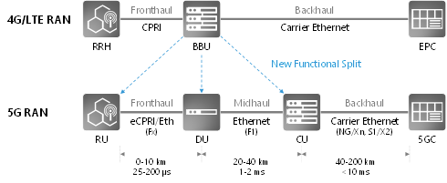
Figure 1. 5G RAN architecture and decomposition
All real-time functions are concentrated in the RU and DU, which makes the F1 interface very similar to the backhaul in terms of data rate and transport characteristics. For the Fx interface, multiple implementation options are possible. It may require 4-5 times higher data rate than the one of the F1 and backhaul interface. More importantly, the eCPRI specification defines an IP/Ethernet layer for Fx transport, as well as latency and synchronization requirements for different service classes and radio configurations [3]. This natively opens up a huge potential to leverage the well-established market scale of Ethernet equipment for the fronthaul transport, and inherits the existing Ethernet protocols for Operations, Administration, and Maintenance (OAM), Control and Monitoring (e.g. SNMP), as well as synchronization.
The trade-off of employing different split options in RAN deployments, or placement of the CU, DU, and RU, is not a clear cut. There is no one-fit-for-all choice, but such a functional decomposition offers more flexibility to design and deploy the transport network. For instance, in large cell sites leveraging carrier aggregation or Coordinated Multi-Point (CoMP), DU and CU can be collocated or integrated to optimize radio resource management. In mm-wave or small cell applications, radio heads may instead integrate the RU and DU.
On the other hand, application demands also indirectly determine or influence the position of radio functions as well. Generally, it is advisable to follow the principle “centralize what you can and distribute what you must”. This is easiest if the latency is not critical. Very low and ultra-low latency applications, though, will require computing at the network or cell edge. DU and CU processing is needed beforehand to facilitate user plane access.
Ultimately, a flexible RAN architecture may support different configurations simultaneously and use radio carriers, frequency bands or network slices to separate them.
3. Transport requirements and challenges
3.1. Bandwidth
The most important transport requirement is the fronthaul capacity per site. In the 5G RAN, the fronthaul throughput generally scales with the actual user traffic on the air interface plus a certain amount of overhead which depends on the particular functional split. Figure 2 depicts the peak transport bandwidth for a single radio sector versus the number of MIMO layers, plotting different required data rates of the Fx and F1 interface for either a 100Mz Sub-6GHz or a 400MHz mm-wave carrier. It shows that the transport bandwidth is proportional to the RF bandwidth and the Fx interface needs approximately 4 times more capacity than the F1 interface. For the summation over multiple sectors and radio sites, NGMN suggests an averaging approach, as it is unlikely that all radio units operate at peak load simultaneously [4]. The required transport bandwidth will also fluctuate over time and largely depend on the radio configuration and user traffic load.
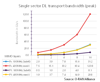
Figure 2. Transport bandwidth comparison between F1 and Fx split
Due to the variable bit rate traffic, the 5G fronthaul can eventually benefit from a packet-based transport solution which enables statistical multiplexing. It is foreseen that 10 to 25 Gbit/s optical interfaces will be adequate for 5G fronthaul in the near term [5]. At large cell sites with multiple RUs, it is feasible and beneficial to aggregate fronthaul traffic to 100 Gbit/s between Cell Site Gateways (CSGs) and DU sites.
3.2. Latency
Latency becomes not only critical, but also an extremely key variable in the 5G transport. For different service types (e.g. eMBB, URLLC, and mMTC), or vertical applications like IoT, industrial, and automobile, different latency budgets are required.
It can be viewed from two aspects: first is user latency in the order of millisecond, measured between the egress of the User Plane Function and the user equipment, and second is latency in relation to processing protocols, such as Hybrid Automatic Repeat Request (HARQ). Delays over the fronthaul interface can lead to performance inefficiency on the RAN Physical layer, and this leads to a stringent latency requirement in the order of 50 to 250 µs round trip time (RTT) between RU and DU. The light propagation time in the fiber is approximately 5 µs/km, which dominates the end-to-end latency. When using Ethernet transport equipment, queuing and buffering also introduce latency from a few microseconds to tens of microseconds, depending primarily on the packet length and line rate. Similar latency contributions also arise when using TDM-based networks, such as the passive optical network (PON) or optical transport network (OTN). Since the forward error correction (FEC) will be largely inevitable for the interface at 25 Gbit/s and beyond, the latency of FEC processing needs also to be taken into account.
However, what is more important is the determinism of latency. The variation in the One-Way Delay (OWD) of packets is called “jitter” (or “delay variation”). Fronthaul packets transported in Ethernet need to arrive within a certain time window at the ingress of radio equipment [6]. Given that the same Ethernet interface may distribute timing information, such as IEEE 1588 Precision Time Protocol (PTP), PDV will result in time error.
4. Optical layer options
As mentioned in the introduction, though it might be quicker to deploy the RAN transport through microwave, MNOs give more considerations to fiber. Apart from performance advantages, optical transport can provide a unified solution for small cells, macro cells, and massive MIMO for both 4G and 5G services. It supports a variety of Ethernet interfaces from 1 to 100 Gbit/s, and even beyond. This unfolds the use of Ethernet Network Interface Devices (NIDs) over a common optical underlay.
Different optical layer options for 5G transport exist, from which operators will likely have to address different network scenarios and use a mix of solutions.
Grey optics are the most flexible and cost-efficient solution in fiber-rich scenarios, where the RU and DU/CU are linked up by direct dark fibers per physical port. The IEEE and other MSAs have defined a variety of interfaces for reaches of FR (2 km), LR (10 km), ER (40 km), and ZR (80 km).
Wavelength division multiplexing (WDM) solutions allow the best exploitation of the fiber capacity and can be deployed as passive, semi-active or active solutions. Passive solutions use pluggable interfaces on both ends, while semi-active and active solutions use transponders on one and both ends, respectively. Dense WDM (DWDM) offers the highest fiber capacity and distance, whereas LAN-WDM and coarse WDM (CWDM) solutions leverage data center optics and can be more cost-effective, if shorter distances and lower fiber capacities are acceptable. An extended LAN-WDM and a medium WDM (MWDM) derivative with 12 wavelengths are in discussion (e.g. O-RAN Alliance, ITU-T G.owdm) to address antenna configurations with 3 sectors and 2 frequencies over a single fiber. However, so far there is no consensus on beyond 25 Gbit/s per lane for LAN-WDM or MWDM.
Time division multiplexing passive optical network (TDM-PON) exploits the fiber-to-the-x (FTTx) technology and is especially interesting in areas where such technology has already been deployed. The high 5G transport bandwidth will require the use of NG-PON2 or next-generation high-speed PON technology at 25 or 50 Gbit/s. While F1 transport is feasible with common PON technology, Fx transport requires a smaller quiet window for ONU detection and a coordinated dynamic bandwidth allocation algorithm (CO-DBA) to meet the stringent Fx latency and timing requirements. Both are currently in discussion in research and standardization.
Figure 3 depicts all three aforementioned optical layer options.
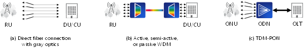
Figure 3. Optical layer options for 5G RAN transport
5. Transport protocol options
With the introduction of F1 and Fx interfaces, 5G front- and mid-haul traffic can be encapsulated in Ethernet frames, either directly or via eCPRI. Using IEEE1914.3-2018 radio-over-fiber encapsulation, legacy CPRI fronthaul traffic can also be transported over Ethernet, positioning Ethernet as convergence layer for consolidating back-, mid-, fronthaul and possibly other packet traffic. The IEEE802.1CM standard leverages Carrier Ethernet and defines new time-sensitive Ethernet transport profiles for fronthaul traffic, taking both CPRI and eCPRI requirements into account, such that frame delay variations of time-sensitive fronthaul traffic can be minimized by strict priority scheduling and optionally preempting lower priority traffic. Additional means such as the asynchronous time window approach or synchronous scheduling of time-sensitive traffic can further reduce latency and frame delay variation in the optical transport network, leading to reduced playout buffers at the terminal [7].
Layer 1 TDM schemes such as an optical transport network (OTN) with 1.25Gb/s or FlexE with 5Gb/s tributary slot granularity are also being discussed as optical x-haul options. FlexE (or G.mtn for metro transport network) perform TDM multiplexing and switching on the Ethernet physical coding sublayer (PCS). Whereas TDM schemes practically eliminate delay variations and reduce latency to a sub-hundred microseconds (OTN) and sub-microsecond scale (FlexE), they lack statistical multiplexing and fine granular traffic management capabilities.
Another rising yet critical requirement from the 5G transport protocol is to deliver timing to the RU. Conventionally, the global navigation satellite system (GNSS) at the cell site provides the reference of pulse per Second (PPS) and Time of Day (ToD), but access to the GNSS satellite signal cannot be guaranteed at all times, and it is vulnerable to the weather condition and even at risk of signal spoofing. Alternatively, the frequency and time information can be distributed from one central source through the network. ITU-T specifies Synchronous Ethernet (SyncE) to transfer a synchronization signal between network elements. It relies on a bit-level clock recovery at each hop and is highly robust for long-term frequency distribution, but it only provides frequency synchronization and every node in the sync path requires physical-layer support for SyncE. Complementing SyncE, the IEEE 1588 PTP [8] provides a mechanism for end-to-end phase and time alignment, as well as frequency distribution if SyncE is not available. However, as a packet-based Layer 2/3 protocol, the performance of PTP can be extremely dependent to the PDV across network elements. ITU-T SG15/Q13 recommends use of SyncE and PTP for 5G fronthaul solutions in ITU-T G.8275.1.
6. Conclusion
Putting all these facts together, Figure 4 summarizes all the different layering options for the optical 5G transport.
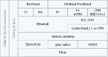
Figure 4. 5G transport layer stack
While Ethernet becomes the converged transport protocol from backhaul to fronthaul, TDM-PON, FlexE and OTN add additional protocol layers. It is worth noting that there is no one-fits-all transport solution. Depending on the available fiber infrastructure, different optical underlay technologies and network topologies (e.g. point-to-point, tree, ring) can be adopted, either standalone or in combination. In any case, an accurate distribution of timing and synchronization information is essential. Operations, administrations and maintenance as well as service assurance functions are necessary for low operational overhead in the deployed solution.
Acknowledgement
This work was supported by the European Union’s Horizon 2020 Research and Innovation Program under Grant Agreement No. 871900 (5G-COMPLETE).
References
1. “Release 16 Description; Summary of Rel-16 Work Items,” 3GPP Tech. Rep. TR21.916, 2020.
2. “Study on new radio access technology: Radio access architecture and interfaces,” 3GPP Tech. Rep. TR38.801, v14.0.0, 2017.
3. “Common Public Radio Interface: Requirements for the eCPRI Transport Network,” CPRI Specification (2018), http://www.cpri.info/spec.html.
4. NGMN Alliance, “5G RAN CU - DU network architecture, transport options and dimensioning,” Public Deliverable, v1.0, Apr. 2019.
5. P. Sehier et al., “Transport evolution for the RAN of the future [Invited],” J. Opt. Commun. Netw., vol. 11, no. 4, B97–B108, Apr. 2019.
6. O-RAN Alliance, “O-RAN Fronthaul Control, User and Synchronization Plane Specification,” O-RAN Specification, v5.0, Nov. 2020.
7. S. Bjørnstad et al., “Minimizing Delay and Packet Delay Variation in Switched 5G Transport Networks”, J. Opt. Comm. Netw., vol. 11, no. 4, B49–B59, Apr. 2019.
8. “Precision Clock Synchronization Protocol for Networked Measurement and Control Systems,” IEEE Std. 1588-2019.
Jim (Shihuan) Zou (M’16) received his B.Eng. degree in communication and information engineering and M.Sc. degree in electrical circuits and systems from Shanghai University, China, in 2008 and 2011, respectively. In 2015, He received the PhD degree from the Eindhoven University of Technology, The Netherlands, where he conducted the fiber-wireless research work. Since 2016, he is with ADVA Optical Networking SE, Germany, currently as principal engineer leading EU research projects in the area of next-gen optical access. He actively participates in the O-RAN Alliance and ITU-T SG15 for RAN standardization contributions. He is also a core member of the Access Solution team under Product Line Management, supporting product design and business development.
Jörg-Peter Elbers (M’00–SM’18) is responsible for technology strategy, applied research, standardization and intellectual property at ADVA. He has more than 20 years of experience in the optical networking industry. Prior to joining ADVA, Jörg held senior technical and leadership roles at Ericsson, Marconi and Siemens. He earned a Dipl-Ing. and Dr.-Ing. degree in electrical engineering from Technical University Dortmund, Germany. Jörg is senior member of the IEEE, heads the German VDE ITG expert committee on communications, and serves on the steering board of the European technology platform on networks (Networld2020). He was technical and general co-chair of OFC 2017 and 2019, respectively, and is member of the European management committee of ECOC. Jörg authored and co-authored more than 150 papers, 5 book chapters, and 20 patents.
Radio Propagation Modelling for Smart Environments in 5G/6G Networks
Jiliang Zhang, Department of Electronic and Electrical Engineering, The University of Sheffield, Sheffield, UK.
Jie Zhang, Department of Electronic and Electrical Engineering, the University of Sheffield, Sheffield, UK, and Ranplan Wireless Network Design Ltd., Cambridge, UK.
Abstract
Over 80% of mobile traffic takes place in buildings. Building layouts and materials have a significant impact on radio propagation in indoor environments. While wireless link capacity is approaching the Shannon limit, optimizing building layouts and modifying material electromagnetic properties become a promising way to enhance in-building wireless communication performance. We foresee that in 6G, smart environments (SEs) enabled by wireless friendly building structures and materials will either interact with wireless networks or be part of them. With SEs, radio channels become much more dynamic, which gives rise to challenges in radio propagation modelling. In this article, we first present the latest results on channel models for SEs with integrated network devices. Then, we examine dynamic radio propagation modelling for SEs with metamaterials (MMs) and intelligent reflecting surfaces (IRSs). Next, we present results on outdoor-indoor radio propagation in neighborhood small cell networks. After that, we shed lights on wireless performance modelling for buildings. Finally, we summarize our key findings and highlight a few research directions on radio propagation modelling for SEs in 6G.
1. Introduction
Over 80% of mobile traffic takes place in buildings [1]. The wireless communication industry has used various network deployment strategies to provide indoor wireless coverage and capacity cost-effectively, for example, relying on outdoor radio base stations (BSs) to provide indoor coverage in the 2G/3G eras, and moving towards, deploying indoor networks to meet both coverage and capacity demands in the 4G era, and densifying the indoor BSs with large-scale antenna arrays (LSAA) to address the increasing traffic demands in the 5G era [2].
Radio propagation model is fundamental for wireless system design, network performance evaluation, wireless protocol comparison, radio network planning and continuous network optimization. Indoor radio propagation models have been investigated in the last few decades. Detailed classifications of state-of-the-art radio propagation models can be found in [3].
Locating most BSs indoors brings new challenges to indoor radio propagation modeling due to the natural complexity of the indoor environment. Current radio propagation models need to be refined as the densification of indoor BSs with LSAAs generates new communication scenarios that have not been well considered in existing channel models.
Moreover, we believe that wireless efficiency is an intrinsic property of a building environment [4-6]. In the future, wireless communications, like the safety, insulation, and daylighting performance, will become a utility for buildings. While designing buildings, architects must consider wireless efficiency of building layouts and building materials carefully.
Therefore, we identify the following new communication scenarios, which are emerging but have not been well investigated in existing channel models.
2. Smart environments with integrated network devices
Indoor BSs equipped with LSAAs are a promising technology to address the capacity crunch problem in-building. However, in order to guarantee a low spatial correlation, the space intervals among antenna elements of the array have to be larger than half wavelength. LSAAs will increase the physical dimension of the BS, generating negative consequences on weight and visual impact. The strict space constraints on antenna housing will force 5G/B5G LSAA design to exploit more advanced technologies to support a higher level of visually obscured integration in the natural surroundings of the users.
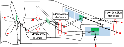
Figure 1. Building material embedded LSAA BS in a typical indoor environment.
Therefore, venue owners/users may prefer to deploy the BSs in positions that will not lead to inconveniencing usages of a room. One possible solution is to deploy BS antennas close to an interior wall of the building. Another potential solution is to embed antennas into building structures, e.g., concrete walls and glasses, as shown in Fig. 1. When deploying the BS antennas close to the wall, the loss caused by the conduction of the material can be avoided in comparison with integrating them into the building structures. In contrast, while integrating the BS antennas into the building material, more antenna elements can be employed in a limited space to facilitate LSAA deployment because the electrical length of the antenna is reduced. Especially in the industrial environment, deploying BSs in the workspace may increase the risk of accidents. Under this situation, the BS antennas must be embedded in building materials.
Therefore, the interactions between the indoor radio propagation and the wall/building material should not be neglected in indoor radio propagation modeling. To investigate the impact of wall on a BS close to it, we have developed a statistic model by integrating the wall reflection multi-path component into the independent and identically distributed Rician channel model [7,8]. Therein, the wall is modeled as a single-layer dielectric. Moreover, we have designed a building material embedded antenna [9] and proposed an empirical model to predict the impact of a single-layer building material on the performance of antenna embedded in it [10].
However, there are still challenges remaining in channel modeling considering the interaction between building materials and BSs with LSAAs. The major challenge is that building materials are not ideal smooth single-layer materials in general. On one hand, the analytical mapping between the MIMO channel matrix and the properties of multi-layer materials is difficult to derive because reflection characteristic is jointly influenced by the incident angle of EM waves as well as each individual material layer’s permittivity and thickness [11]. On the other hand, the surface of the building materials may not be smooth enough, and thus, the wave is diffused [12]. How to model the radio propagation considering the interaction between the BS and the rough building material is still unknown. Moreover, the properties of the building material may be inhomogeneous. When modelling the indoor radio propagation, we cannot know the exact EM properties of the building material in advance, and therefore, the size of antenna element and antenna array may not match the building material well. When modelling indoor radio propagation, we have to investigate its robustness on the inhomogeneity of EM properties.
3. Metamaterial-aided communications
With the emergence of smart built environments, MMs are considered as a key technology in 6G mobile communications. MMs enable innovative ways for communications such as switching walls between unidirectional and bidirectional modes [13], using toric/parabolic surfaces that homogenize the strength of the indoor signal [14,15], and using intelligent reflecting surfaces (IRSs) to control multipath components [16,17] and improve the degree of freedom (DoF) of MIMO channel by integrating multiple scattering elements [18]. In the indoor environment, it is natural to assume that all MMs are mounted on building structures. The application scenarios of MMs under indoor environments can be summarized as in Fig. 2.
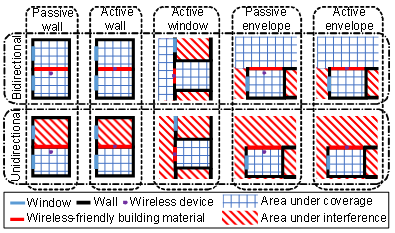
Figure 2. Typical application scenarios of MMs in indoor environments.
Most of the state-of-the-art works on radio propagation modelling with MMs consider the MM as a device. In recent works, pathloss models of EM wave reflected by MMs have been measured and modelled [19,20]. The pathloss models reveal that how MMs generate controllable multipath components. A future research direction is to model radio propagates in an MM-integrated indoor environment considering the controllable multipath components generated by the MM.
4. Pure neighborhood small cell
While deploying BSs in-building, the leakage power from buildings could be made use of by an outdoor user that cannot be satisfied by outdoor BSs. From this perspective, the novel neighborhood small cell (NSC) network system has been proposed [21,22]. Conventionally, outdoor users are either jointly served by NSC BSs and macro-cell BSs or switch between NSC networks and macro-cell networks.
Due to urbanization, indoor small-cell (SC) BSs are densified naturally to address the increasing traffic demands. Considering that: (1) most users are located indoors, and (2) macro-cell BSs cost high deployment operation and significant energy consumption [23], we foresee that the hybrid macro-cell/NSC network will be replaced by a pure NSC network in the dense urban area [24]. In the pure NSC network, indoor SC BSs need to serve outdoor users via indoor-to-outdoor (I2O) signal transmission. To offset the penetration loss of the building envelope, CoMP techniques [25] will be applied.
Outdoor-to-indoor (O2I) radio propagation has been well investigated considering the conventional coverage of indoor users by macro-cell BSs [26]. However, published works on the I2O radio propagation modelling are relatively scarce. O2I radio propagation model cannot be directly applied in the I2O scenario using reciprocity. In the O2I scenario, the outdoor macro-cell BS is mounted above rooftop levels of surrounding buildings. Whereas in the I2O scenario, the outdoor user is located on the ground, so that the radio propagation characteristics are different from the O2I scenario.
Therefore, I2O radio propagation has to be further investigated for the NSC network design, evaluation, deployment and optimization. Future research directions for I2O radio propagation modelling are outlined as follows. Firstly, the impact of building material-BS interaction on the I2O radio propagation needs to be investigated, as in 3.1. Secondly, the correlation between links from different indoor SC BSs has to be taken into account because it significantly impacts the performance of CoMP technologies [27,28]. Thirdly, the penetration loss of building structures for various building layout needs to be empirically modelled to provide tractable but sufficiently accurate tools for NSC evaluation.
5. Building wireless performance modelling
As the link level throughput is approaching the Shannon capacity limit nowadays, improving wireless communication systems alone is no longer feasible nor cost effective to address the exploding indoor data traffic. Hence, it is now urgent to investigate how to design and modify indoor environment to enhance the building wireless efficiency (BWE).
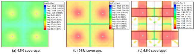
Figure 3. Impact of building designs on indoor wireless coverage, predicted by the intelligent ray-launching algorithms in Ranplan Professional® [39].
BWE has never been used in the building design process. As a result, the desirable BWE may be unachievable in a built environment. For the first time, we have identified the idea that every building has an intrinsic wireless performance which is independent of how densely small cells are deployed. In this Section, we review our ground-breaking work that bridges building design and wireless network deployment.
5.1 Wireless-efficient building layouts
Intuitive examples of good or bad building layout in terms of BWE are illustrated in Fig. 3. Four transmit single-antenna elements with the same transmit power are evenly distributed to provide a benchmark. Coverage rate is computed assuming a 5 dB SINR threshold. It is predictable that for building layouts shown in Fig. 3(a, c), it is difficult to obtain a straightforward wireless deployment solution to achieve a coverage rate of 96%, which can be easily achieved in the building plan in Fig. 3(b). These examples demonstrate the importance of building design on in-building wireless performance.
The first step towards the building layout evaluation is to investigate the line-of-sight (LOS) probability while the BS and the user is randomly located in the building. In 3GPP channel model, the empirical LOS model is provided without consideration of building layout [26]. In [29], we, for the first time, derived an analytical LOS probability model for specific building layouts. In [30], the proposed model was extended to 3-D scenarios. In [31], a machine learning-based empirical LOS probability model is proposed with inputs of statistical building layout features.
Funded by a Eurostars project Build-Wise, which was ranked the 16th in 331 applications [32] in 2016 September competition, we have presented ground-breaking works that systematically evaluate building layouts in terms of wireless efficiency. (1) The interference gain (IG) and power gain (PG) were defined as two figures of merit (FoM) to evaluate the wireless efficiency of a building layout [33]. (2) To quickly and accurately compute the FoMs, an approach to derive exact closed-form expressions for these FoMs was proposed in [5]. (3) Based on the IG, we developed a novel approach to compute the optimum transmitting power to achieve the maximum IG of a building layout [6]. The proposed approaches and numerical result shed light to architects on evaluation and design of building layouts with desirable wireless efficiency, and to radio engineers on how to approach the intrinsic wireless performance of a building.
In the scope of wireless-efficient building layouts, we identify the following research directions. Firstly, impact of building layouts on other metrics such as area spectral efficiency should be applied to evaluate BWE. Secondly, the trade-off between the maximal tolerable density of transmit elements and the maximal achievable BWE needs to be comprehensively investigated. Thirdly, a building’s wireless performance considering spatially correlated shadowing should be considered. Moreover, future analysis will include a comprehensive building wireless performance evaluation considering diverse types of buildings such as office, shopping mall, airport, stadium and train station.
5.2 Wireless-efficient building materials
Building structures and materials significantly affect wireless communications in-building. New building materials and structures that achieve better BWE while keeping good physical properties needs to be well designed. However, how to design building materials to achieve adequate BWE has never been systematically researched. Identifying the wireless efficiency of building materials, we have defined two H2020 MSCA-Individual Fellowships, AceLSAA [34] and GATE [35]. The GATE project achieved 98.8% and was ranked 6th among over 900 applications in the ENG panel.
To lay a foundation for investigating the wireless efficiency of building materials, we have measured the EM properties of building materials. In [36], complex permittivity of four typical building materials, i.e., ceramic, granite, PVC, and wood, was extracted from practical measurement based on a vector network analyzer. In [12] and [37], we presented a measurement campaign of diffuse scattering pattern from six typical building materials, i.e., granite, marble, plasterboard, wooden board, rough stone and ceramic tile, over a frequency range from 40 GHz to 50 GHz. In [40], we presented a three-step minimum least square-based algorithm to accurately resolve two closely adjacent rays reflected from the front and the back surfaces of a board-shaped material while measuring the EM properties of building materials.
We have designed metrics that capture the wireless efficiency of building materials for simple single-layer building materials while putting the BS close to a wall. In [7], we defined the ergodic capacity in a room covered by the BS as a metric to evaluate the wireless efficiency of the wall. In [8], we defined the per-antenna power distribution as a metric to evaluate the impact of wall on the efficiency of the power amplifier in a BS equipped with LSAA.
In the scope of wireless-efficient building materials, we identify the following research directions. Firstly, more application scenarios, as listed in Fig. 2, should be considered while evaluating wireless efficiency of building materials. Secondly, we will evaluate the wireless efficiency of building materials while embedding BSs with LSAA into them. Thirdly, we will optimize composite building materials and MM-based building materials for better BWE. Fourthly, building materials will be designed and optimized targeting good BWE while keeping acceptable physical properties such as anisotropic strength, stiffness, and optical transparency. Finally, advanced building material manufacturing technologies, such as 3D concrete printing, will be applied to prototype wireless efficient building materials. Moreover, the building layout and building materials need to be jointly evaluated and optimized in terms of wireless efficiency.
In summary, our key findings on radio propagation modelling for SEs in 6G is listed in TABLE I.
Table 1. list of our contributions on radio propagation modelling for smart environments.
| Publications | Research direction |
| [7-10] | Smart environments with integrated network devices |
| [24,38] | Pure neighborhood SC |
| [6,29-31,39] | Wireless efficient building layouts |
| [12,36,37,40] | Wireless efficient building materials |
6. Conclusions
In the future, indoor radio propagation environment must be well designed to meet the requirement of future wireless traffic demand. In this review paper, we summarized studies of indoor radio propagation models and identified future research directions for intelligent indoor radio propagation environment. Beyond indoor radio propagation, the indoor environment itself should be carefully evaluated, modelled and optimized at the building design stage. Our current and future outcomes in this research direction will shed light to architects and civil engineers on design, evaluation and optimization of wireless-efficient building layouts and materials.
References
1. Cisco, “5G-thriving indoors, Cisco White Paper,” https://www.cisco.com/c/dam/en/us/solutions/collateral/serviceprovider/ultra-services-platform/5g-ran-indoor.pdf. Accessed: 20/04/2021.
2. J. G. Andrews, et al., “What will 5G be?” IEEE J. Sel. Area Commun., vol. 32, pp. 1065-1082, 2014.
3. C. X. Wang, et al., “A survey of 5G channel measurements and models,” IEEE Commun. Survey & Tut., vol. 20, no. 4, 2018.
4. EUROSTARS Project 11088 BuildWise (The development of a software tool to design buildings with tailored wireless performance), https://www.eurostars-eureka.eu/project/id/11088. Accessed: 20/04/2021.
5. J. Zhang, et al., “Wireless performance evaluation of building layouts: Closed-form computation of figures of merit,” IEEE Trans. Commun., early access.
6. J. Zhang, et al., “Wireless energy efficiency evaluation for buildings under design based on analysis of interference gain,” IEEE Trans. Veh. Tech., vol. 69, no. 6, pp. 6310-6324, 2020.
7. Y. Zhang, et al., “How friendly are building materials as reflectors to indoor LOS MIMO communications?,” IEEE Internet Things J., vol. 7, no. 9, pp. 9116-9127, Sept. 2020.
8. Y. Zhang, et al., “Effects of wall reflection on the per-antenna power distribution of ZF-precoded ULA for indoor mmWave MU-MIMO transmissions,” IEEE Commun. Lett., vol. 25, no. 1, pp. 13-17, Jan. 2021.
9. Y. Yao, et al., “Design of glass-integrated grid antenna using CMA for multiband indoor network,” ISAP, 2020.
10. J. Tan, et al., “Empirical formulas for performance prediction of concrete embedded antenna,” ISAP, 2020.
11. ITU-R, “Effects of building materials and structures on radiowave propagation above about 100 MHz P series radiowave propagation,” Recomm. ITU-R P.2040-1, Jul. 2015.
12. X. Liao, et al., “Experimental study of diffuse scattering from typical construction materials over 40-50GHz,” IEEE APCAP, 2018, pp. 216-218.
13. L. Subrt, et al., “Advanced modelling of intelligent walls for indoor smart environments,” EuCAP, 2014.
14. R. Kitta, et al., “Research of the indoor reflection wave control with phase control wall,” ISAP, 2012.
15. H. D. Hristov, et al., “Indoor signal focusing by means of Fresnel zone plate lens attached to building wall,” IEEE Trans. Ant. Prop., 2004.
16. M. D. Renzo, et al., “Smart radio environments empowered by reconfigurable AI meta-surfaces: An idea whose time has come,” EURASIP J. Wireless Commun. Netw., vol. 129, no. 1, May 2019, Art. no. 129.
17. E. Basar, et al., “Wireless communications through reconfigurable intelligent surfaces,” IEEE Access, vol. 7, pp. 116753-116773, Aug. 2019.
18. Ö. Özdogan, et al., “Using intelligent reflecting surfaces for rank improvement in MIMO communications,” IEEE ICASSP, 2020
19. W. Khawaja, et al., “Coverage enhancement for NLOS mmwave links using passive reflectors,” IEEE Open J. Commun. Soc., vol. 1, pp. 263-281, Jan. 2020.
20. Ö. Özdogan, et al., “Intelligent reflecting surfaces: Physics, propagation, and pathloss modeling,” IEEE Wireless Commun. Lett., vol. 9, no. 5, pp. 581-585, May 2020.
21. Qualcomm Inc., “Neighborhood small cells for hyper dense deployments: Taking HetNets to the next level,” White Paper, Feb. 2013.
22. N. Bhushan, et al., “Network densification: The dominant theme for wireless evolution into 5G,” IEEE Commun. Mag., vol. 52, no. 2, pp. 82-89, Feb. 2014.
23. W. Guo and T. O’Farrell, “Capacity-energy-cost tradeoff in small cell networks,” IEEE VTC, 2012, pp. 1-5.
24. W. Yang, et al., “On evaluation of indoor to outdoor communications using neighbourhood small cells,” IEEE Trans. Veh. Technol., vol. 69, no. 7, pp. 8045-8050, July 2020.
25. D. Gesbert, et al., “Multi-cell MIMO cooperative networks: A new look at interference,” IEEE J. Sel. Areas Commun., vol. 28, no. 9, pp. 1380-1408, Dec. 2010
26. 3GPP, “Study on channel model for frequencies from 0.5 to 100 GHz (3GPP TR 38.901 version 14.3.0 Release 14),” 2018.
27. J. Zhang, et al., “Indoor multiple-user MIMO channel measurement and characterization,” IEEE CAMAD, 2018, pp. 1-5
28. L. Ding, et al., “Investigation of spatial correlation for two-user cooperative communication in indoor office environment,” IEEE ICCT, 2010, pp. 420-423
29. H. Zheng, et al., “Exact line-of-sight probability for channel modeling in typical indoor environments,” IEEE Ant. Wireless Prop. Lett., vol. 17, no. 7, pp. 1359-1362, July 2018
30. W. Yang, et al., “Line-of-sight probability for channel modeling in 3-D indoor environments,” IEEE Ant. Wireless Prop. Lett., vol. 19, no. 7, pp. 1182-1186, July 2020
31. W. Yang, et al., “Machine learning based indoor line-of-sight probability prediction,” ISAP, 2019, pp. 1-3.
32. https://www.eurostars-eureka.eu/project/id/11088. Accessed: 20/04/2021.
33. Ranplan Wireless Network Design, “Method for evaluating the building wireless performance,” Patent, 2020.
34. https://cordis.europa.eu/project/rcn/212652/factsheet/en. Accessed: 20/04/2021.
35. https://cordis.europa.eu/project/id/843133. Accessed: 20/04/2021.
36. J. Luo, et al., “Complex permittivity estimation for cloths based on QPSO method over (40 to 50) GHz,” IEEE Trans. Ant. Prop., vol. 69, no. 1, pp. 600-605, Jan. 2021
37. H. Tian, et al., “Effect level based parameterization method for diffuse scattering models at millimeter-wave frequencies,” IEEE Access, vol. 7, pp. 93286-93293, 2019.
38. W. Yang, et al., “On performance of ultra-dense neighborhood small cell networks in urban scenarios,” IEEE Commun. Lett., vol. 25, no. 4, pp. 1378-1382, April 2021.
39. www.ranplanwireless.com. Accessed: 20/04/2021.
40. J. Zhang, et al., “Two-ray reflection resolution algorithm for planar material electromagnetic property measurement at the millimeter-wave bands,” Radio Science, vol. 55, no. 3, pp. 1-14, March 2020.
 Jiliang Zhang (M'15, SM’19) received the B.E., M.E., and Ph.D. degrees from the Harbin Institute of Technology, Harbin, China, in 2007, 2009, and 2014, respectively. He was a Postdoctoral Fellow with Shenzhen Graduate School, Harbin Institute of Technology from 2014 to 2016, an Associate Professor with the School of Information Science and Engineering, Lanzhou University from 2017 to 2019, and a researcher at the Department of Electrical Engineering, Chalmers University of Technology, Gothenburg, Sweden from 2017 to 2018. He is now a Marie Curie Research Fellow at the Department of Electronic and Electrical Engineering, The University of Sheffield, Sheffield, UK.
He serves as an Academic Editor for the Wireless Communications and Mobile Computing and a Topic Editor for the Electronics. His current research interests include, but are not limited to wireless channel modelling, modulation system, relay system, vehicular communications, ultra-dense small cell networks, and smart environment modelling.
 Jie Zhang has held the Chair in Wireless Systems at the Department of Electronic and Electrical Engineering, University of Sheffield (www.sheffield.ac.uk) since Jan. 2011.
He is also Founder, Board Director and Chief Scientific Officer (CSO) of Ranplan Wireless (www.ranplanwireless.com), a public company listed on Nasdaq OMX. Ranplan Wireless produces a suite of world leading indoor and the only joint indoor-outdoor 5G/4G/WiFi network planning and optimization tools suites including Ranplan Professional and Collaboration-Hub, which are being used by the world’s largest mobile operators and network vendors across the globe.
Along with his students and colleagues, he has pioneered research in small cell and heterogeneous network (HetNet) and published some of the landmark papers and books on these topics, widely used by both academia and industry. Since 2010, he and his team have also developed ground-breaking work in modelling and designing smart built environments. His Google scholar citations are in excess of 7800 with an H-index of 38.
Prior to his current appointments, he studied and worked at Imperial College London, Oxford University, University of Bedfordshire, and East China University of Science and Technology (PhD in 1995), reaching the rank of a Lecturer, Reader and Professor in 2002, 2005 and 2006, respectively.
Millimeter-wave Metantenna Technologies in 5G and Beyond
Zhi Ning Chen, Department of Electrical and Computer Engineering, National University of Singapore
Abstract
The antenna is one of the most important technologies in all modern wireless networks. The deployment of new wireless systems always creates new technical challenges or opportunities for the development of antenna technologies from radiators to systems. The concepts of metamaterials have broken the boundaries of the conventional EM engineering. In particular, the applications of metasurfaces, a new design concept of two-dimensional EM structures, have offered the new opportunities to the innovative antenna technology. This article addresses the challenges and progress in the development of metamaterial/metasurface-based antennas, metantennas in short, in 5G millimeter-wave bands. Four design examples from 2 cases of flat lenses, a shared aperture to a dual-band metantennas demonstrate the applications of metantennas for 5G network. Of them one example of three-beam metalens antenna operating at 5G New Radio 2-GHz bands is also selected because the design method can be directly extended to the designs at millimeter-wave bands. The success in the applications of metantennas has shown the promising way for developing the antennas for new functionalities and new performance levels in 5G and beyond networks.
1. Challenges and Innovation of Antenna Technologies in 5G and Beyond
The innovations of 5th generation mobile network (5G) are rapidly changing wireless technology from network architecture to unit design (such as antenna technologies) because of the new and ambitious technical and application vision. In particular, new multiple antenna technologies have been the focus of innovation since the early stage of 5G. They include but are not limited to the antennas to support:
- massive multiple input multiple output (mMIMO) systems,
- multiuser-MIMO systems,
- multiple radio access technology systems;
- pattern reconfigurable and beam switchable systems;
- multiple-beam and phased beamsteering systems; and
- aperture sharing systems.
The antenna technology has significantly advanced to more and more complicated systems since 3G mobile network to match to the requirements for larger and larger capacity with huge number of connections and Gbps data-rates for both uplink and downlink, as well as higher and higher resolution and less and less latency for sensing. The requirements for advanced antenna systems have raised the challenges relevant to antennas such as:
- increased antenna design complexity;
- increased antenna system integration complexity and cost;
- increased overall volume, particularly, horizontal size for tower/roof basestation antennas; and
- increased power consumption.
Meanwhile the new spectra with wider bandwidths have been proposed to meet the new performance expectations mentioned above. Besides the new sub-6GHz bands, from 3GPP TS 38.101-1, the bands of n257, n258, n260 and n261 of Frequency Range 2 have been allocated for 5G systems. The available frequency ranges from 24.25 GHz to 40.00 GHz, covering higher K-band and Ka-bands or the lower edge of millimeter-wave (mmW) bands. The shorter wavelengths at mmW bands to some degree ease the challenge of large physical volume of large-scale multiple antenna systems compared to the antenna systems operating at sub-6GHz bands. With the physical limitation of propagation of electromagnetic waves at mmW bands, the antennas used for mmW links are usually high in gain to compensate for high pathloss [1]. Therefore, the high-efficiency antenna or array designs at mmW bands becomes top critical.
2. Innovation of Antenna Technologies: Metantennas
Antenna technology is about a system including radiators or an array of radiators, controlling units, and signal processing [2]. As the hardware, the radiators, namely antennas have been very well developed since Heinrich Hertz’s days. The most important recent innovation of antennas should be the applications of metamaterial concepts in antenna design since later 1990s.
Metamaterial is a general physical concept to describe all artificial structures which electromagnetic properties have been not found in nature. Usually, such structures are described using material parameters such as permittivity, permeability, or refractive index. Its two-dimensional versions, namely metasurfaces are characterized using the parameters such as transmission, reflection, or polarization conversion. The metamaterial concepts have removed the boundary of natural materials so that metamaterial-based antennas, metantennas in short, can be the inventions with new functionalities or enhanced performance of existing designs [3]. For example, either effective permittivity or effective permeability of the structures can range from negative to positive infinite. The metasurface can be used a wave transformer to manipulate the amplitude, phase, and polarization in a large range but through an electrically very small distance (small thickness). With such boundaryless unique properties, the control of electromagnetic wave features more freedom. As a result, this has offered great opportunity for innovative antenna design. So far, it has been well proven that the metantennas can be used to enhance almost all the key performance of existing antennas in terms of, for example,
- miniaturization of antenna volume and lowering antenna profile;
- enhancement of antenna gain with acceptable efficiency;
- widening antenna bandwidth of impedance, gain, and phase responses;
- suppressing mutual coupling between antennas;
- control of antenna radiation patterns by shaping beam, pointing beam, or suppressing sidelobe levels;
- design electrically large current zero-phase-shift loops; and
- control of near-zone magnetic field using artificial magnetic materials with high, zero, or negative permeability.
The metantennas have been successfully applied over whole microwave bands. Here the metantennas invented for 5G mmW operation are exemplified to demonstrate the applications of metantennas. For sure, the technology developed can be naturally scaled down or up for the designs at adjacent bands.
3. Metantennas at 5G mmW Bands: Design Examples
There have been more and more metantenna designs at mmW bands for 5G network [4]. For example, the flat metasurface lenses for high gain, multibeam, and spatial massive MIMO applications, flat metasurface reflectarray, planar metasurface antennas for dual-band operations, shared aperture metasurface antenna, and so on.
3.1 Flat Metasurface Lens
Full dielectric lens antennas usually feature high focusing performance such as high aperture efficiency for high gain, flexibility of multiple functionalities such as the generation of multiple beams, but suffer from bulky and costly three-dimensional design, in particular, at microwave bands. With the metasurfaces, it is possible to flatten the conventional dielectric lenses and fabricate the lenses using printed circuit board (PCB) technology. Metasurface is a two-dimensional arrangement of electrically thin engineering polarized scatterers to control the phase, amplitude, and polarization of EM waves over its surface for desired functions. A dielectric focusing lens achieves the phase distribution to compensate for the phase difference of a spherical EM wavefront using varying dielectric thickness of a lens. Similarly, the unit cells on a metasurface are design to realize varying phase shifts for phase compensation.
Design 1: With metasurfaces a flat multiple beam lens antenna operating at 28 GHz was designed for spatial multiple-input and multiple-output (MIMO) systems as shown in Figure 1 [5]. Figure 1a shows the mechanism of a conventional double-convex dielectric lens. With the varying thickness the lens realizes the phase shift distribution over its aperture so that the spherical wavefront of EM radiated from lens focal point to planar wavefront and vice versa. If a bilayer metasurface can achieve the same phase shift distribution over the aperture as the dielectric lens, the bulky dielectric lens can be replaced by the metasurface based structure, metalens in short. The metasurfaces consists of two arrays of unit cells printed onto two pieces of PCB. The metasurfaces are separated by air. Use of two layers is to enhance the phase shift range of the metalens. The unit cells achieved high transmission coefficients, typically higher -1 dB, and dynamic phase shift range, desired 0~360 degrees over the frequency range.
Figure1b shows the photo of prototype of a planar lens antenna fed with seven feeding antennas. The metalens antenna operates at a 28-GHz band of 5G network. With the seven feeding antennas located near focal arc achieve a scanning coverage of ±27° with a gain of 20.5-24.2 dBi. The achieved aperture efficiency is 24.5% over the bandwidth of 26.6-29 GHz. The designed metalens antenna features the advantages of compact size, low cost, lightweight, simple feeding network, and easy integration with other circuits over the conventional dielectric lens antennas.
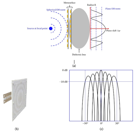
Figure 1. (a) conventional dielectric lens and metasurface-based metalens, and (b) prototype with seven feeding antennas and seven beams generated by the feeding antennas.
Design 2: It is challenging to apply lens antennas in lower microwave bands, for instance around 2 GHz, very popular frequency bands for 5G New Radio network. The application of lens antennas is naturally good candidates for the achievement of multiple beams within an existing antenna aperture. For instance, the conventional signle beam of halfpower-beamwidth of 90 degrees can be divided into three identical beams each of 30 degrees, pointing to the directions of 0 and 30 degrees.
Figure 2 shows a compact wideband wide-angle polarization-free metalens antenna array for a three-beam base station operating over the band of 1.71-2.2 GHz for 5G New Radio [6]. Figure 2a show the three beams with coverage of ±30° range compared with conventional single beam design.
Figure 2b shows the cross-section view of the metalens antenna. The five-layered metasurface consists of arrays of rectangular elements, which are relatively smaller for wideband, wide-angle, polarization-free, and reflectionless responses. The metalens is excited by three pairs of antennas of ±45° polarized cross-dipole antennas.
Within limited space the challenges include the miniaturization of the antennas, optimization of radiation patterns, and suppression of mutual coupling between the feeding antennas. With bent ground plane the three pairs of antennas symmetrically located generate the three beams in the directions of 0° and ±30° in a horizontal plane. As a section of array with 1×4 elements, the antenna achieves the isolation larger than 22.3 dB over an impedance bandwidth of 1.63-2.24 GHz for return loss ≥ 10 dB. The measured gain ranges / the sidelobe levels are 11.8-13.5 dBi / -22.6 dB for 0° beam and 10-12.2 dBi / -13.6 dB for 30° beams, respectively.
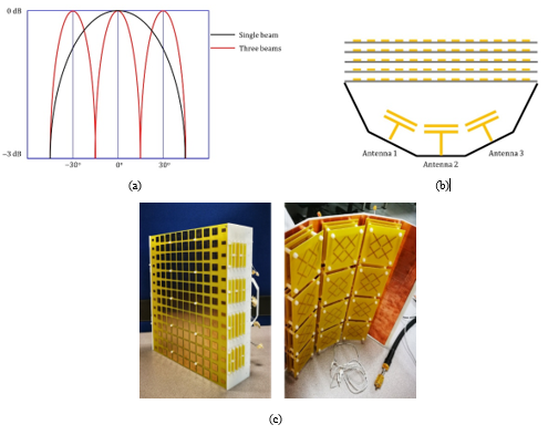
Figure 2. (a) Three beams vs single beam, (b) cross-section view of metalens antenna, and (c) photos of prototypes of three-beam metalens antenna.
Besides the design examples, there have been many lens technologies have been developed for high-gain and multi-beam applications for 5G network at microwave bands. Sharing the same principle as transmissive metalens antennas, the reflective metasurfaces have also been developed for high-gain applications. More selected references can be found in References [7-21] .
3.2 Metasurface Antennas
With the introduction of multiple mmW bands into 5G network, antenna design has more considerations. For instance, sharing the aperture of antenna is a promising way not to increase the aperture of antenna when the antennas operating at new mmW bands are integrated into the existing antennas operating at lower bands.
Design 3: Figure 3 shows a dual-band shared-surface antenna operating at both 5G 3.5-GHz and 28-GHz bands [22]. The antenna integrates a 33-unit-cell metasurface operating at the 3.5-GHz band and an 1818-unit-cell partially reflective surface at the 28-GHz band. The antenna simultaneously achieves the operations at both the 3.5-band and 28-band with 10-dB impedance bandwidth of 23.5% and 9.8% as well as the realized gain of 7.3 ~ 10.4 dBi and 11.8 ~ 14.6 dBi, respectively.
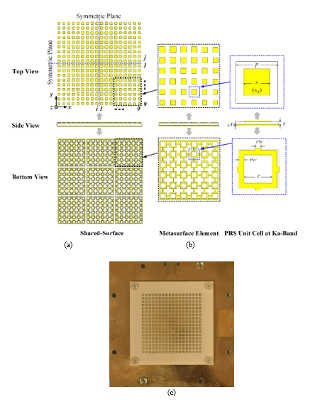
Figure 3. (a) Shared aperture, (b) metasurface, partial reflection sheet and their unit cells, and (c) the photo of antenna prototype. (The figures (a) and (b) from Ref. 22)
Importantly, the radiation patterns at both 3.5-GHz and 28-GHz bands keep unchanged as original designs as shown in Figure 4. It suggests that the operations at two bands share the same aperture without interference. This will benefit the designs operating at multiple bands for high integration of multiple antennas.
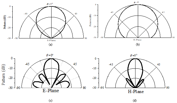
Figure 4. Normalized radiation patterns. (a) E-plane at 3.6 GHz, (b) H-plane at 3.6 GHz, (c) E-plane at 28 GHz, and (d) H-plane at 28 GHz.
Design 4: Figure 5(a) demonstrates a compact metasurface-based antenna with 3 × 3 square patch unit cells for 5G 28-GHz and 38-GHz bands [23]. Using a characteristic mode analysis (CMA), the patch unit cells of the antenna are modified and optimized to operate at three modes resonating at 28 GHz, 33 GHz, and 36 GHz, respectively. Excited by a substrate integrated waveguide feeding network, the proposed metantenna achieves the 10-dB measured impedance bandwidths of 23.7-29.2 GHz and 36.7-41.1 GHz as shown in Figure 5(b). the achieved gain reaches 4.8-7.2 dBi and 8.9-10.9 dBi over the two bands, respectively.
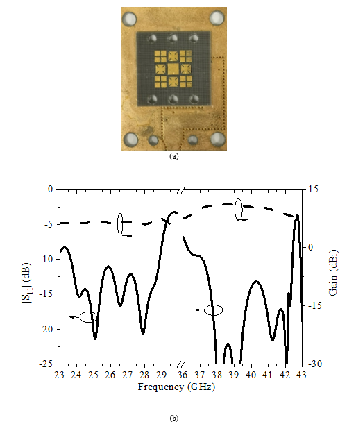
Figure 5. (a) Photo of prototype of the dual-band antenna and (b) |S11| GHz and gain for 3.6-GHz and (c) 28-GHz bands.
Similar to Design 3, the most challenging design consideration is to achieve consistent radiation patterns over the dual bands. Three modes operating with desired similar radiation patterns are selected to operate at the two bands based on the results by CMA. The three selected modes are excited to realize the patch-like radiation patterns over both the bands as shown in Figure 6.
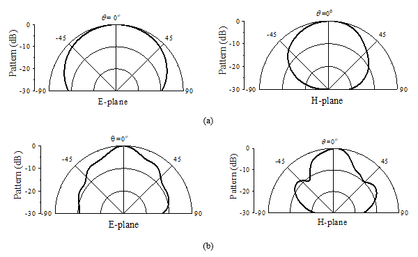
Figure 6. Normalized radiation patterns at (a) 26 GHz and (b) 38.5 GHz bands.
4. Conclusion
The antenna is the most classic technology in the history of radio engineering. Rapid development of applications has spurred the innovation of antenna technology because of the fact that the performance of antennas in classic forms has quickly approached their physical limits. With the realization of metamaterials, in particular, metasurfaces featuring unique EM properties, we have one more opportunity to invent new antennas, metantennas with enhanced performance, reduced volume, and even new functions.
In the past decade, our team has focused the research and development of metamaterial/metasurface/metaline based antennas, namely, metantennas at microwave bands for satellite communications (SatCom), automotive radar, radio-frequency identification (RFID), wireless local area network (WLAN), magnetic resonance imaging (MRI), and base stations of 5G network.
The fast evolution of wireless systems like 5G is advancing conventional antenna technology to the new generation at radiator and system levels. The development and adoption of new physical concepts and new mathematic methods such as metamaterials and artificial intelligent enabled design and optimization methods will definitely create the opportunities for the innovation of antenna technologies.
Acknowledgements
Thank all team members who have contributed to the work mentioned in this article. Special thanks go to Dr Teng Li from Southeast University, China and Karlsruhe Institute of Technology, Germany for his help in preparing the manuscript.
About Author Zhi Ning Chen (M’99-SM’05-F’07) received his BEng (1985), MEng (1988), and PhD (1993) degrees all in Electrical Engineering from the Institute of Communications Engineering (ICE), Nanjing, China and his second PhD (2003) degree from the University of Tsukuba, Tsukuba Japan, respectively.
In 2012, Dr Chen joined the Department of Electrical and Computer Engineering, National University of Singapore as a Professor and currently as Deputy Director of Advanced Research and Technology Innovation Center as the founder.
Dr Chen has published 680+ academic papers and six books and is holding 33 granted/filed patents. he is more interested in metasurfaces based antennas.
Dr Chen was elevated the Fellow of Academy of Engineering, Singapore in 2019 and a Fellow of the IEEE for the contribution to small and broadband antennas for wireless applications in 2007. Currently he is serving IEEE Future Networks Initiative Tech Focus Editorial Board as a member. He has served IEEE Council on RFID as a Distinguished Lecturer since 2016 and as a Vice President during 2015-2020. He severed IEEE Transaction on Antennas and Propagation as an Associate Editor and IEEE Antennas and Propagation Society as a Distinguished Lecturer as well as the members of Fellow Committee and New Direction Committee. (www.ece.nus.edu.sg/staff/bio/czn.html)
References
[1] Z. N. Chen and X. Qing (ed.), Substrate-Integrated Millimeter-Wave Antennas for Next-generation Communication and Radar Systems. IEEE Press /Wiley, May 2021
[2] Z. N. Chen and K. M. Luk (ed.), Introduction in Antennas for Base Stations in Wireless Communications. McGraw Hill, page xxi. 2009
[3] T. Li and Z. N. Chen, “Metantennas: MultiFunctional Metasurface Antennas,” International Conference on Electromagnetics in Advanced Applications (ICEAA), Granada, Spain, 9-13 Sept. 2019, pp. 121–125.
[4] Z. N. Chen, T. Li, M. Jiang, W. E. I. Liu, and X. Qing, “Millimeter-Wave Metantennas for 5G Wireless Communications (Invited),” IEEE Asia-Pacific Microwave Conference (APMC), Singapore, 2019, pp. 31-32, doi: 10.1109/APMC46564.2019.9038738.
[5] M. Jiang, Z. N. Chen, Y. Zhang, W. Hong, and X. Xuan, “Metamaterial-Based Thin Planar Lens Antenna for Spatial Beamforming and Multibeam Massive MIMO,” IEEE Transactions on Antennas and Propagation, vol. 65, no. 2, pp. 464-472, Feb. 2017, doi: 10.1109/TAP.2016.2631589.
[6] T. Li and Z. N. Chen, “Compact Wideband Wide-Angle Polarization-Free Metasurface Lens Antenna Array for Multibeam Base Stations,” IEEE Transactions on Antennas and Propagation, vol. 68, no. 3, pp. 1378-1388, March 2020.
[7] Y. Su and Z. N. Chen, “A flat dual-polarized transformation-optics beamscanning Luneburg lens antenna using PCB-stacked gradient index metamaterials,” IEEE Trans. Antennas Propag., vol. 66, no. 10, pp. 5088–5097, Oct. 2018.
[8] Y. Su and Z. N. Chen, “A radial transformation-optics mapping for flat ultra-wide-angle dual-polarized stacked GRIN MTM Luneburg lens antenna,” IEEE Trans. Antennas Propag., vol. 67, no. 5, pp. 2961–2970, May 2019.
[9] Z. N. Chen, Y. Su, and W. E. I. Liu, “Metantennas: Flat Luneburg Lens Antennas Using Transformation Optics Method (TOM),” International Workshop on Antenna Technology (iWAT), Bucharest, Romania, 25-28 Feb. 2020.
[10] S. Li, Z. N. Chen, T. Li, F. H. Lin and X. Yin, “Characterization of Metasurface Lens Antenna for Sub-6 GHz Dual-Polarization Full-Dimension Massive MIMO and Multibeam Systems,” in IEEE Transactions on Antennas and Propagation, vol. 68, no. 3, pp. 1366-1377, March 2020.
[11] C. Xue, Q. Lou, and Z. N. Chen, “Broadband Double-Layered Huygens’ Metasurface Lens Antenna for 5G Millimeter-Wave Systems,” in IEEE Transactions on Antennas and Propagation, vol. 68, no. 3, pp. 1468-1476, March 2020.
[12] M. Imbert, J. Romeu, M. Baquero-Escudero, M. Martinez-Ingles, J. Molina-Garcia-Pardo and L. Jofre, “Assessment of LTCC-Based Dielectric Flat Lens Antennas and Switched-Beam Arrays for Future 5G Millimeter-Wave Communication Systems,” in IEEE Transactions on Antennas and Propagation, vol. 65, no. 12, pp. 6453-6473, Dec. 2017, doi: 10.1109/TAP.2017.2767821.
[13] A. Dadgarpour, M. Sharifi Sorkherizi, and A. A. Kishk, “High-Efficient Circularly Polarized Magnetoelectric Dipole Antenna for 5G Applications Using Dual-Polarized Split-Ring Resonator Lens,” in IEEE Transactions on Antennas and Propagation, vol. 65, no. 8, pp. 4263-4267, Aug. 2017, doi: 10.1109/TAP.2017.270809.
[14] M. S. Rabbani, J. Churm and A. Feresidis, “Electro-Mechanically Tunable Meta-Surfaces for Beam-Steered Antennas from mm-Wave to THz,” 2020 50th European Microwave Conference (EuMC), Utrecht, Netherlands, 2021, pp. 416-419, doi: 10.23919/EuMC48046.2021.9338142.
[15] S. I. Naqvi, M. A. Azam, Y. Amin, J. Loo and H. Tenhunen, “Beam-Steerable Antenna Array with Metasurface at Millimeter Wave Frequency Range,” 2019 22nd International Multitopic Conference (INMIC), Islamabad, Pakistan, 2019, pp. 1-6, doi: 10.1109/INMIC48123.2019.9022785.
[16] M. Wu, K. Kosaka, and E. Hankui, “Reconfigurable Metasurface Lens Thin Antenna with 3-State Unit Cells in 28-GHz Band,” 2019 IEEE International Symposium on Antennas and Propagation and USNC-URSI Radio Science Meeting, Atlanta, GA, USA, 2019, pp. 1599-1600, doi: 10.1109/APUSNCURSINRSM.2019.8888622.
[17] M. Xue, W. Wan, Q. Wang, and L. Cao, “Low-Profile Millimeter-Wave Broadband Metasurface Antenna with Four Resonances,” in IEEE Antennas and Wireless Propagation Letters, doi: 10.1109/LAWP.2021.3053589.
[18] J. Yin, Q. Wu, Q. Lou, H. Wang, Z. N. Chen, and W. Hong, “Single-Beam 1 Bit Reflective Metasurface Using Prephased Unit Cells for Normally Incident Plane Waves,” IEEE Trans. Antennas Propagat., vol. 68, no. 7, pp. 5496-5504, July 2020.
[19] Z. N. Chen, T. Li, and W. E. I. Liu, “Microwave Metasurface-based Lens Antennas for 5G and Beyond,” 14th European Conference on Antennas and Propagation (EuCAP 2020), Copenhagen, Denmark, March 15-20, 2020.
[20] Z. N. Chen, “Microwave Metalens: A Classic but New Antenna Solution,” 2020 Asia-Pacific Microwave Conference (APMC), 8-11 December, 2020 Hong Kong, China
[21] C. Xue, Q. Lou and Z. N. Chen, "Broadband Double-Layered Huygens’ Metasurface Lens Antenna for 5G Millimeter-Wave Systems," in IEEE Transactions on Antennas and Propagation, vol. 68, no. 3, pp. 1468-1476, March 2020, doi: 10.1109/TAP.2019.2943440.
[22] T. Li and Z. N. Chen, “Shared-Surface Dual-Band Antenna for 5G Applications,” in IEEE Transactions on Antennas and Propagation, vol. 68, no. 2, pp. 1128-1133, Feb. 2020, doi: 10.1109/TAP.2019.2938584. (sub-6GHz+28GHz)
[23] T. Li and Z. N. Chen, “A Dual-Band Metasurface Antenna Using Characteristic Mode Analysis,” in IEEE Transactions on Antennas and Propagation, vol. 66, no. 10, pp. 5620-5624, Oct. 2018, doi: 10.1109/TAP.2018.2860121.
CSAI: Open-Source Cellular Radio Access Network Security Analysis Instrument
Thomas Byrd and Vuk Marojevic, Mississippi State University
Roger Piqueras Jover*, Bloomberg LP
∗Author did not contribute to source code. Code published to accompany this paper was written by Mr. Thomas Byrd and Dr. Vuk Marojevic.
IEEE Future Networks Tech Focus, Issue 12, April 2021
Abstract
This paper presents our methodology and software toolbox that allows analyzing the radio access network security of laboratory and commercial 4G and future 5G cellular networks. We leverage a free open-source software suite that implements the LTE UE and eNB enabling real-time signaling using software radio peripherals. We modify the UE software processing stack to act as an LTE packet collection and examination tool. This is possible because of the openness of the 3GPP specifications. Hence, we are able to receive and decode LTE downlink messages for the purpose of analyzing potential security problems of the standard. This paper shows how to rapidly prototype LTE tools and build a software-defined radio access network (RAN) analysis instrument for research and education. Using the Cellular Security Analysis Instrument (CSAI), a researcher can analyze broadcast and paging messages of cellular networks. CSAI is also able to test networks to aid in the identification of vulnerabilities and verify functionality post-remediation. Additionally, we found that it can crash a software eNB which motivates equivalent analyses of commercial network equipment and its robustness against denial of service attacks.
Index Terms—open-source LTE, SDR, paging, radio access network signaling, analysis, wireless security
1. Introduction
The long-term evolution (LTE) is a cellular communications standard developed by the 3rd Generation Partnership Project (3GPP). LTE was finalized in 3GPP Release 8 in December 2008, and LTE-Advanced followed in 3GPP Release 10. Only recently has there been significant enough open source software development efforts for producing stable implementations of the LTE and LTE-A specifications to allow for rapid prototyping and testing of 4G networks by the broader research community.
Next generation 5G networks promise a huge leap from 4G. The reality however is that the initial 5G releases leverage LTE networks in many regards: New Radio (NR) initially implements a similar radio access network (RAN) and hooks to LTE’s evolved packet core (EPC). 5G generally allows more flexible waveform and protocol configurations, transmission in sub 6 GHz and millimeter wave bands, and higher band- widths than LTE. The waveform will initially be orthogonal frequency division multiplexing (OFDM) and the 5G signaling frame will carry user data and control information.
There is a huge need for research and development tools that enable cellular signaling analysis for a multitude of purposes. It can help understand the limitations of current implementations and guide the evolution of the standard. They can also be effectively used for education and training. Security is another important aspect where RAN signaling analysis is needed. It has been shown that the LTE control signaling suffers from targeted interference that an adversary can exploit, easily and cheaply [1]. We therefore propose a flexible signal analysis tool for analyzing commercial and experimental cellular communication systems, assisting in the detection of potential vulnerabilities, and evaluating correc- tive measures which will pave the path to secure wireless networks.
We leverage open-source software implementations of LTE and introduce the free and open-source Cellular Security Analysis Instrument (CSAI) in this paper. CSAI is lightweight and can process data in real time. It interfaces with common software radio hardware, such as Ettus Research USRPs, and can capture LTE control messages and be extended to capture 5G NR signals. It can emulate an eNodeB (eNB) or user equipment (UE) and implement specific processes to test the behavior of the UE or eNB. It also allows testing larger RANs which involve multiple UEs or multiple eNBs. For example, in commercial networks that have dozens of UEs, or more, that rotate between serving cells, this tool will be able to monitor paging traffic in a particular cell and identify new UEs as they are paged for analysis.
It is very important to be able to analyze protocol edge cases and understand their implications in terms of RAN security. Not only can it be used for examining the standard specifications of a modern cellular standard, but this tool can also test vendor specific implementations. Additionally, it is a benchmarking tool for stress testing 4G and 5G networks and can be adapted to fit different use cases. For instance, if a vendor needs an automated tool to determine the limits of their Radio Resource Control (RRC) buffers, this instrument will be able to facilitate that.
The remainder of this paper is organized as follows. Section II briefly outlines other work in the area of capturing LTE messages and performing LTE security analyses. Section III describes the important LTE signaling procedures over the RAN. This allows for better comprehension of Section IV, which introduces CSAI, our software instrument for analyzing broadcast and paging messages, among others. Section V discusses experiments and data collected from commercial networks. Section VI focuses on the security implications of our initial results, and Section VII concludes the paper.
2. Related Work
Security research of cellular communications standards has a long history and helped evolve systems to the current 4G and emerging 5G networks [2]. The insecure 2G systems are still used today and whenever 4G or 3G coverage is not available, handsets look for 2G networks. 4G systems introduce network and user authentication, where a user can authenticate the network it connects to. However, certain 4G security vulnerabilities were identified that 5G networks intend to fix.
With the emergence of software radios, increasing process- ing power of general-purpose computers, and software imple- mentations of cellular standards, experimental LTE security research took off [3]. Researchers dissected the entire LTE signaling frame looking for vulnerabilities of the system when specific subsystems are interfered with. Two types of attacks were examined, control channel jamming and spoofing, and mitigation mechanisms were proposed in [4] and [5]. Other research groups tested LTE’s higher layer signaling protocols and published their findings in open literature [6].
While there exist many commercial tools that perform LTE traffic capture and decoding, to our knowledge, there is no open source software that will accomplish this. Papers that have been published regarding LTE security require the use of commercial LTE capture tools or the development of custom tools as observed in [7] and [8]. The relevance of this subject is apparent from the availability of professional test instruments, offered by various hardware and software companies. But their high cost limits their widespread use in research and education. Our goal is to provide a framework for making cellular RAN signaling analysis accessible to all, enable wireless security research, increase the transparency and visibility of RAN operations, and allow easy adoption by industry and standardization bodies.
3. Background
This section provides the necessary background on how LTE UEs register to the network and get notified by the network of incoming messages or calls. When a UE powers on, it first needs to receive and decode the Primary and Secondary Synchronization Signals (PSS/SSS) [9]. Together, these two signals allow the UE to synchronize on a slot and frame level basis, respectively, as well as correct for frequency offsets between the eNB and UE oscillators. Now that the UE is synchronized with the eNB, it needs to know more information about the serving network before it can initiate an attach request. Therefore, it decodes the Master and System Information Blocks (MIB/SIBs). These blocks are transmitted in the clear by the eNB on a regular basis to ensure that UEs have the necessary information needed to attach. This is the initial cell search that each UE performs when turned on or when returning out of coverage and is part of the information that our tool can capture and analyze.
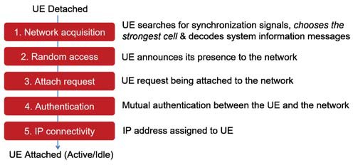
Figure 1. The LTE UE attachment process.
Once a UE knows the network configuration details that are provided in the MIB/SIBs, it can then use its Random Access Radio Network Temporary Identity (RA-RNTI) to initiate a RRC connection with the eNB. After a UE has established an RRC connection, the UE will communicate to the EPC through the eNB over the Non-Access Stratum (NAS) protocol layer. Fig. 1 illustrates this attachment process.
In order to identify themselves, UEs utilize the International Mobile Subscriber Identity (IMSI). This secret identifier can be leveraged in a number of privacy-invading attacks [10] and, as such, should always be kept private. However, the UE will authenticate with the EPC’s Home Subscriber Server (HSS) transmitting its IMSI in the clear if the UE has no history with the network.
Once all of the NAS and RRC connections are established, the UE will enter an Idle state and deactivate the radio link between itself and the eNB. If the EPC needs to deliver a message to an idle UE, it is the job of the eNB to wake-up the idle device and re-establish a physical connection [11]. This is done by sending out a paging message to UEs in the operational area of the eNB. Paging messages use a specific Paging RNTI (P-RNTI) [12] to indicate the broadcast nature of paging and UEs are required to respond if their IMSI or System Architecture Evolution (SAE) Temporary Mobile Subscriber Identity (S-TMSI) is being paged. The S-TMSI is a combination of the Mobility Management Entity (MME) Code and the Mobile TMSI (m-TMSI); herein both are simply referred to as the TMSI. Our tool is able to capture and decode the SIBs and paging messages for specified eNBs, which enables performing RAN security analyses.
4. CSAI
There are numerous ways to analyze the LTE RAN. These range from expensive commercial cellular test equipment to open source GNU Radio implementations that provide insight into cellular networks. We chose srsLTE [13] for its simplicity and applicability toward analyzing LTE signals and messages.
srsLTE implements 3GPP Release 8 with certain compo- nents of Release 9 integrated into its software. It is licensed under the GNU Affero General Public License for free use for non-commercial purposes, such as research and education. The srsLTE software suite is compatible with software defined radio (SDR) hardware to build LTE networks. As the names suggest, srsUE implements the LTE UE and srsENB the LTE eNB. To accompany these, Software Radio Systems (SRS) has also published srsEPC which provides an Evolved Packet Core (EPC) that is needed for a fully working LTE network with one or several eNBs serving one or several UEs. At the time of experimentation, we are using the most current version of srsLTE, version 18.12.0 based on commit 3cc4ca85 from the master branch [14].
CSAI implements the ability to capture cellular paging messages and information blocks along with capabilities to stress test RRC connections. Both of these features are achieved by modifying the srsUE source code. Specifically, we modify the code that implements the RRC protocol. The RRC protocol is primarily responsible for connection establishment and release as well as handling paging messages. In the connection_request function, send_con_request is called which is responsible for sending the RRC connection request message to the lower layers that is transmitted to the eNB. If we comment this function and replace it with a call to rrc_conection_release, we instruct the UE to remain disconnected and not communicate with the eNB. This alone allows capturing the SIBs transmitted by the eNB, but is not enough to capture paging messages.
In order to capture paging messages, we add an additional line after the connection release call to update the RRC state to reflect a successful connection. The other layers of srsUE will now look for paging messages and they are automatically captured and logged. Figures 2 and 3 give examples of captured information blocks and paging messages.
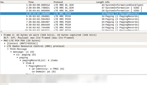
Figure 2. Wireshark analysis of paging messages.
5. Analysis
In order to benchmark CSAI, we capture commercial net- work traffic and provide masked statistics to show the effec- tiveness of the tool. Two USRP B210s with the modifications detailed in Section IV were used to capture SIBs and paging traffic on an Ubuntu 18.04.02 computer. Similarly to [15] and [16], only SIB and paging messages were acquired; careful consideration was taken to ensure that no user data was captured or retained despite being encrypted.
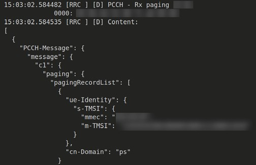
Figure 3. Log output of paging message.
A. Short-Term Persistence
Table I shows the data that we obtained from three net- works. We measured the amount of total paging traffic over a five to six hour time frame of two network operators the first day, and repeated the same capture for the third operator on the following day. By inspecting the paging information to see whether IMSIs were used to page users, we found that all pages used S-TMSIs to identify a UE as opposed to revealing the IMSI, which is an encouraging result.
The last row in Table I indicates the longest observed TMSIs in minutes which match the lengths of the experiments. In all three cases, several TMSIs were observed throughout the capture, but the majority of TMSIs were either a single occurrence, or were used for a short time.
Table 1. Network Statistics
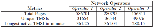
Figure 5 shows the histograms of the lifespans of the observed TMSIs. Most TMSIs are very short lived, whereas some are observed for the entire duration of 6 hours. Our measurements were taken at a single location and we had no control of the UEs in the area. Due to the mobility of users, it is likely that the average TMSI lifespan is longer than shown here. Operator 1 has a significant number of long- lasting TMSIs. This implies that many UEs attached to this cell did not hand-off connectivity during our experiments, or that cellular Operator 1 does not rotate TMSIs as frequently.
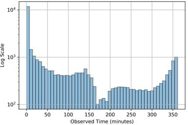
(a) Operator 1
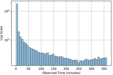
(b) Operator 2
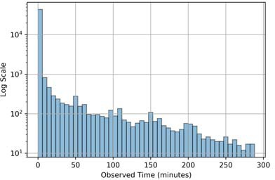
(c) Operator 3
Figure 4. Time distribution of observed Paging messages.
B. Long-Term Persistence
We examine the persistence of TMSIs and for this use two commercial UEs and CSAI. We initiate communication from one UE to the other and capture the paging messages. This is accomplished by sending numerous messages from one UE to the other with ample time between messages so that the RRC connection is released due to UE inactivity. The next day we repeated a similar communication pattern to generate more paging messages to our UE.
We review the log files to see if our TMSIs from day one persisted on the following day. While the test was limited in scope, we did not observe any of the TMSIs from day one in the day two logs. This is a particularly encouraging result, as it implies that this network operator rotates TMSIs at least every day.
C. Potential Attacks
CSAI takes advantage of the inherent nature of pre- authentication and broadcast signaling in LTE. While paging messages do not inherently contain sensitive information, it is possible to map a TMSI to a RNTI if you monitor subsequent RRC connection setup requests. Once a mapping is obtained, an attack as described in [17] could allow for statistical traffic analysis even though the content of the NAS messages are encrypted.
Lichtman et al. outline several attacks in [1]. Once the MIB/SIBs are decoded, it is possible to target jamming efforts towards a specific eNB. Combined with the aforementioned TMSI to RNTI mapping, it would be possible to extend the attack and jam one or several UE’s data and control plane traffic.
Most network operators will page a UE using a TMSI; however, the 3GPP standard allows eNBs to page a UE using its IMSI in cases where a UE does not respond to three subsequent paging attempts using a TMSI. This presents a sig- nificant security issue as many follow-on attacks are capable once a UEs IMSI is known and include down bidding attacks or man in the middle style interceptions as demonstrated in [7] and [8]. Our instrument enables research on security analysis and system hardening. Researchers will benefit from CSAI as they test modifications to 4G and 5G protocols to prevent the exploitation of pre-authentication messages [18].
D. Crashing a Software eNB
Another interesting behavior that we observed in the course of developing CSAI was the potential for a straightforward denial of service attack against an SDR eNB through active RF attacks that mimic older Transmission Control Protocol (TCP) synchronize (SYN) flood attacks. When modifying the RRC handshake source such that a UE sends an RRC Connection Request to an eNB and immediately begins the RRC Connection Release process, the UE will not respond to the eNBs request for RRC Connection Setup. The eNB will allocate resources for the UE expecting the UE to reply with an RRC Connection Setup Complete; however, the UE has already begun the process of releasing the connection. This leaves the base station in a half open state waiting for the UE to finish the RRC handshake. Since the UE was instructed to release the RRC connection, after a short delay it will attempt to reconnect to the eNB, further exhausting its resources. A fake UE could constantly request and release RRC connec- tions thus identifying the eNBs maximum capacity for RRC connections, and potentially crashing the eNB.
We performed this attack against an SDR eNB and observed that it crashed due to automated buffer overflow protections enabled by default when using the GNU C Compiler. An example of this crash is shown in Fig. 6.
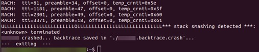
Figure 5. Crash of a software eNB.
Whereas more testing is required to determine the scope of this active attack, one potential mitigation may be similar to how SYN cookies mitigate TCP SYN Flood attacks as detailed in [19], where the eNB would only allocate resources for RRC connections after the UE responds with the full Setup Complete message. It is possible to modify CSAI to include a delay that ensures the eNB does not crash, but rather denies service to legitimate UEs that are connected or are trying to connect. This finding exemplifies the potential of fuzzing attack analysis against cellular networks. Ideally, commercial equipment would have timeout thresholds to prevent a mali- cious RRC flood attack. We are currently investigating this using commercial femtocells with the objective to evaluate their protection mechanisms against the attacks demonstrated above and those discussed in [20].
6. Conclusions
This paper describes how an SDR LTE implementation of a cellular RAN can be repurposed for analyzing the security of wireless networks. Our example is for 4G LTE, but similar principles can be applied to other cellular communications protocols. Using the modifications described in Section IV, SIBs and paging messages are able to be passively recorded from experimental or commercial LTE networks. We also discussed another modification that allows for testing RRC layer limits which can result in a denial of service attack.
CSAI [21] is a community resource that can be used and modified for supporting research using advanced wireless testbeds, such as AERPAW [22]. In continuing research, we are using CSAI as we investigate practical attacks against UE and eNB implementations and their remedies. These include base station/small-cell fuzzing, location leakage, and UE denial of service attacks and their countermeasures.
Acknowledgement
The work of V. Marojevic was supported in part by the NSF Platforms for Advanced Wireless Research (PAWR) program under grant number CNS-1939334. The work of T. Byrd was supported in part by Mississippi State University’s James Worth Bagley College of Engineering, Bobby and Judy Shackouls Honors College, Department of Electrical and Computer Engineering, and NSF’s CyberCorps(R) Scholar- ship for Service program under grant number DGE-1565484.
References
- M. Lichtman et al., “LTE/LTE-A jamming, spoofing, and sniffing: threat assessment and mitigation,” IEEE Commun. Mag., vol. 54, no. 4, pp. 54–61, 2016.
- R. P. Jover and V. Marojevic, “Security and protocol exploit analysis of the 5g specifications,” IEEE Access, vol. 7, pp. 24 956–24 963, 2019.
- R. M. Rao, S. Ha, V. Marojevic, and J. H. Reed, “LTE PHY layer
vulnerability analysis and testing using open-source sdr tools,” in IEEE MILCOM 2017, pp. 744–749. - V. Marojevic, R. M. Rao, S. Ha, and J. H. Reed, “Performance analysis of a mission-critical portable lte system in targeted rf interference,” in IEEE VTC-Fall 2017, pp. 1–6.
- M. Labib, V. Marojevic, J. H. Reed, and A. I. Zaghloul, “Enhancing the robustness of lte systems: analysis and evolution of the cell selection process,” IEEE Commun. Mag., vol. 55, no. 2, pp. 208–215, 2017.
- S. Hussain, O. Chowdhury, S. Mehnaz, and E. Bertino, “LTEInspector: A systematic approach for adversarial testing of 4G LTE,” in Network and Distributed Systems Security (NDSS) Symposium 2018, 2018.
- A. Shaik, R. Borgaonkar, N. Asokan, V. Niemi, and J.-P. Seifert, “Practical attacks against privacy and availability in 4G/LTE mobile communication systems,” arXiv preprint arXiv:1510.07563, 2015.
- R. P. Jover, “Lte security, protocol exploits and location track- ing experimentation with low-cost software radio,” arXiv preprint arXiv:1607.05171, 2016.
- 3GPP, “Evolved Universal Terrestrial Radio Access (E-UTRA); Physical channels and modulation,” Technical Specification (TS) 36.211, 03 2013, version 10.7.0. [Online]. Available: https://portal.3gpp.org/desktopmodules/Specifications/SpecificationDetai ls.aspx?specificationId=2425
- T. Engel, “Locating mobile phones using signalling system 7,” in 25th Chaos communication congress, 2008.
- A. Shrut, “LTE for layman (part 3) - the complete picture!” 2016, [Online; posted 15-June-2016].
- 3GPP, “Evolved Universal Terrestrial Radio Access (E-UTRA); Medium Access Control (MAC); Protocol specification,” Technical Specification (TS) 36.321, 04 2019, version 15.5.0. [Online]. Available: https://portal.3gpp.org/desktopmodules/Specifications/SpecificationDetai ls.aspx?specificationId=2437
- I. Gomez-Miguelez et al., “srslte: an open-source platform for lte evolution and experimentation,” in ACM WiNTECH, 2016, pp. 25–32.
- Software Radio Systems, “srslte,” https://github.com/srsLTE/srsLTE/ tree/3cc4ca851a18b15234d849a5a4a8f9bf0768d30f, 2019.
- S. R. Hussain, M. Echeverria, O. Chowdhury, N. Li, and E. Bertino, “Privacy attacks to the 4G and 5G cellular paging protocols using side channel information,” 2019.
- M. Chlosta, D. Rupprecht, T. Holz, and C. Po¨pper, “LTE security disabled misconfiguration in commercial networks,” in Proceedings of the 12th ACM Conference on Security & Privacy in Wireless and Mobile Networks, ser. WiSec ’19, 2019.
- D. Rupprecht, K. Kohls, T. Holz, and C. Po¨pper, “Breaking LTE on layer two,” in IEEE Symposium on Security & Privacy (SP), 2019.
- M. A. Ferrag, L. Maglaras, A. Argyriou, D. Kosmanos, and H. Janicke, “Security for 4g and 5g cellular networks: A survey of existing authentication and privacy-preserving schemes,” Journal of Network and Computer Applications, vol. 101, pp. 55–82, 2018.
- J. F. Kurose and K. W. Ross, Computer Networking: A Top-Down Approach (7th Edition), 7th ed. Pearson, 2016.
- H. Kim, J. Lee, L. Eunkyu, and Y. Kim, “Touching the untouchables: Dynamic security analysis of the LTE control plane,” in Proceedings of the IEEE Symposium on Security & Privacy (SP), May 2019.
- T. Byrd, “CSAI,” https://github.com/tkb140/CSAI, 2019.
- V. Marojevic, I. Guvenc, M. Sichitiu, and R. Dutta, “An experimental research platform architecture for UAS communications and network- ing,” in IEEE VTC2019-Fall, Sep. 2019, pp. 1–5.
 Roger Piqueras Jover is a senior security architect with the CTO Security Architecture Team at Bloomberg, where he is a technical leader in mobile security architecture and strategy, corporate network security architecture, wireless security analysis and design, and data science applied to network anomaly detection. He is a technology adviser on the security of LTE/5G mobile networks and wireless short-range networks for academia, industry, and government.
Vuk Marojevic received the M.S. degree in electrical engineering from the University of Hannover, Germany, and the Ph.D. degree in electrical engineering from UPC-Barcelona Tech. He was assistant professor at UPC (2008-2012), research faculty at Wireless @ Virginia Tech (2013-2018) and is currently an Associate Professor with the Department of Electrical and Computer Engineering at Mississippi State University. His research interests are in software-defined radio, spectrum sharing, vehicular communications technologies and systems, and resource management with application to public safety and mission-critical networks and unmanned aircraft systems.
Rethinking of Optical Transport Network Design for 5G/6G Mobile Communication
Chathurika Ranaweera, Deakin University, Australia
Ampalavanapillai Nirmalathas, Elaine Wong, Christina Lim, The University of Melbourne, Australia
Paolo Monti, Marija Furdek, Lena Wosinska, Chalmers University of Technology, Sweden
Björn Skubic, Ericsson Research, Sweden
Carmen Mas Machuca, Technical University of Munich, Germany
IEEE Future Networks Tech Focus, Issue 12, April 2021
Abstract
Driven by the increasing use of emerging smart mobile applications, mobile technology is continuously and rapidly advancing towards the next generation communication systems such as 5G and 6G. However, the transport network, which needs to provide low latency and reliable connectivity between hundreds of thousands of cell sites and the network core, has not advanced at the same pace. This article provides insight into how we can solve the fundamental challenges of implementing cost-optimal transport and 5G and beyond mobile networks simultaneously while satisfying the network and user requirements irrespective of the radio access network's architecture.
1. Introduction
The fifth generation (5G) mobile technology promises higher bandwidth capacities, lower latencies, and higher reliability for emerging time-sensitive and mission-critical applications [1]. According to Cisco, the number of connected devices will reach 500 billion by 2030, a number significantly higher than the expected world population. Providing connectivity for billions of devices and satisfying the stringent quality of service requirements of diverse applications is becoming a significant challenge. To address this ongoing issue, academia and industry recently started researching the sixth generation (6G) mobile technology [2].
6G mobile technology expects to provide 100 Gbps or higher data rates and ultra-low latency over ubiquitous 3D coverage areas. However, the transport network, which interconnects the cell sites with the network core, has not progressed at the same pace. For this reason, it has been identified as a potential bottleneck for high-performance and cost-efficient network deployment. Therefore, in order to fulfill the new and miscellaneous requirements of 5G and beyond mobile networks that are arising from the deployment of hundreds of thousands of wireless cell sites, increasingly diverse architectures, and sophisticated applications and services, “the transport network will require to undergo an evolutionary change with a complete rethink of the design and deployment strategies”.
In particular, optical technologies are positioned to be the most sustainable for the transport segment of 5G and beyond networks due to their inherent features such as secure data transmission and high capacity [3]. However, with the decreasing cell size and higher numbers of cells deployed, it becomes harder and more expensive to connect them to the network core with the optical network [4]. This is made even more challenging, given the diverse architectural requirements of radio access networks (RANs) of next-generation (xG) mobile networks [5]. Therefore, new methods are needed to jointly plan and design an xG RAN with its transport network while reducing the cost and meeting all the service requirements. In this article, we present new strategies that we can be applied to plan a 5G/6G network together with its optical transport infrastructure to provide ubiquitous, reliable, and cost-effective access for emerging applications.
2. Network Planning Strategies for 5G and Beyond
To support the unprecedented growth of mobile traffic, RAN has been undergoing diverse changes that directly impact the performance and cost of the network. Consequently, several RAN architectures have been proposed in the recent years. A future RAN may consist of multiple RAN architectures as shown in Fig. 1. The network architecture shown Fig.1 comprises multiple RAN architectures and their transport networks.
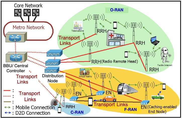
Figure 1. Radio Access Network Architectures for 5G and Beyond
The centralized RAN (C-RAN) is one such paradigm in which the processing of mobile signals is carried out at the centralized base band unit (BBU) placed at the central office (CO). Consequently, in C-RAN, the remote radio heads (RRHs) placed at the cell sites have a very limited set of functions [6]. With the help of virtualization technology few other variants of C-RAN have been proposed and standardized including Open and Intelligent RAN (O-RAN) and fog RAN (F-RAN) [7,8]. In these RANs, the BBU can be further separated and radio control functions can be moved into the cloud, while the radio processing functions remain closer to the cell site, enabling functionalities like network slicing [7].
There is one thing in common irrespective of the RAN architecture in use, that is the requirement of reliable and cost-effective data transportation between RRH and CO. Each of these RAN architectures have different functions at BBU, the RRH and/or distribution node placed between the RRH and CO. These different options are standardized under the IEEE 1914 Next Generation Fronthaul Interface – NGFI (x-haul) [9]. Figure 2 shows 10 different RAN functional split options under consideration. For example, O-RAN considers functional split options 7.2 and 6 [7].
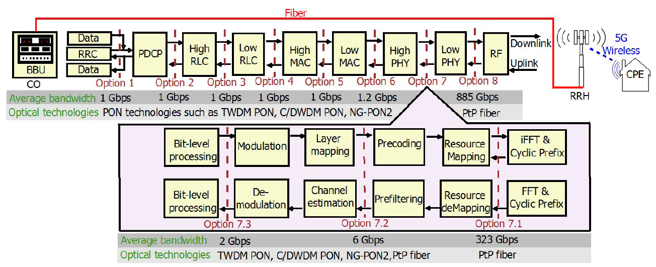
Figure 2. Functional Split Options [12]
The most important thing here is that the bandwidth required for the transport network varies with the functional split option. For example, under average 5G data rates, Option 1 where all functionalities are implemented at the cell site/RRH requires 1 Gbps of bandwidth in the transport (x-haul) link as we only need to transmit packetized processed data. On the other hand, if we use Option 8 where all the functions are centralized at BBU we need more than 800 Gbps on the transport link [10]. In Options 1-6, the bandwidth requirement scales with the number of active users and their traffic because only upper layer functions are centralized, while physical layer functions stay in the RRH. However, after Option 6, bandwidth requirement of x-haul increases exponentially as the bandwidth requirement depends on the physical parameters such as number of antenna ports because now, we move the physical layer functions to the BBU.
Now the challenge is to find the cost-effective and efficient transport network solution because different optical technologies can be used in the transport network depending on the x-haul bandwidth requirement. For example, up to Option 7.3, we can use the cost-effective point to multipoint (PMP) optical links such as passive optical networks (PON) and low data rate point to point (PtP) optical links. However, beyond Option 7.3, we have to use multiple high capacity PtP optical links [11]. In order to achieve the cost-effectiveness and effective operation, we now need to deploy several functional split options and optical technologies in a single network. This is a major challenge.
Therefore, we developed a generalized optimization framework that can be used to jointly plan both 5G wireless and optical transport network for all the functional split options whilst satisfying diverse network requirements such as coverage and capacity. Our framework is also capable of leveraging the resources associated with existing infrastructure to reduce cost and can be used in situations where we have limited availability of existing fiber resources. So that we can apply the framework to analyze the deployment cost and optimally plan the network under any given scenario and to identify the most effective design option. We develop the framework as an integer linear program. In this article, we present an overview of the framework. The details of the mathematical formulation of the framework can be found in [12].
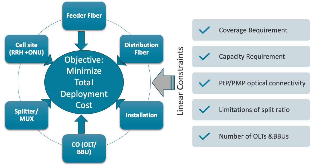
Figure 3. The Optimization framework
Figure 3 illustrates the major components of the framework. As can be seen, the objective of the model is to minimize the total deployment cost of both 5G and its optical transport network. The total deployment cost consists of the cost of feeder fiber, the cost of distribution fiber (deployment of new fiber routes including trenching), the cost of equipment and installations we need at several locations such as CO (BBU, Optical line terminal (OLT) and line cards), splitter location (Splitter /MUX) and cell site (RRH and Optical network unit (ONU)). The framework also consists of multiple constraints to satisfy the network requirements such as coverage, capacity, split ratios, PtP/PMP connectivity and number of BBUs and OLTs in one location. The framework outputs the optimal locations of RRH/ONUs, splitters/MUXs, BBU placement and optimal fiber routes to deploy transport network.
3. Evaluating effectiveness of planning strategies
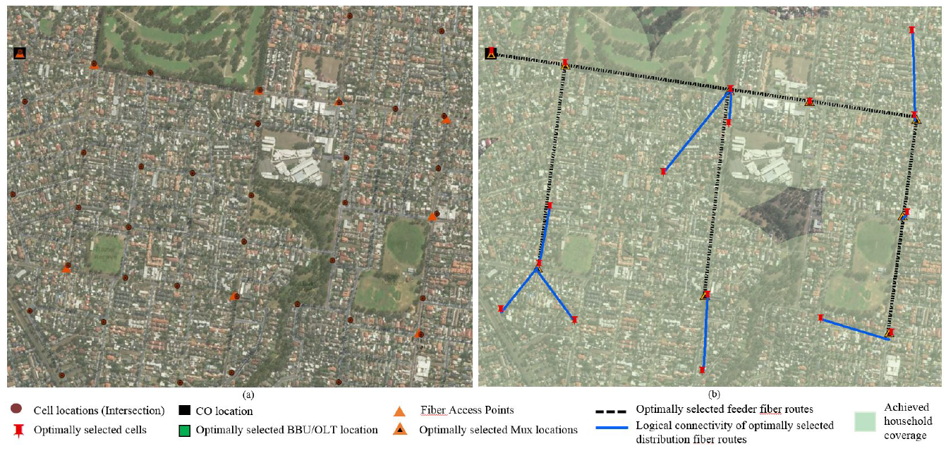
Figure 4. (a) Data set (b) Example of an optimal solution
We then validate our framework by using it to plan 5G and its optical transport network for a suburban area in Eastern Australia. The map of the considered suburban area with over 6000 residents is shown in Fig. 4 (a). The major intersections shown in brown dots are the possible locations for cell deployment, where a light pole/traffic light pole can be used to easily deploy small cells. Orange triangles are the existing fiber access points which are considered as the possible locations for splitter/MUX deployment and black squares are the locations of existing COs. The cost components we applied for the analyses can be found in [12].
We use CPLEX to solve the framework under diverse deployment scenarios considering the fixed wireless access deployment. For example, Fig. 4 (b) shows the optimal solution for the deployment scenario when we have functional split Options 1 to 6, dense wavelength division multiplexing (DWDM) PON as the transport network, RRHs have 300m radius and set the coverage requirement to 99% and per household capacity requirement to 25 Mbps. Figure 4 (b) shows the optimally selected locations for BBU, MUX, RRHs and fiber routes. Feeder fibers are optimally selected from the set of existing fiber network (black dotted lines) and the blue lines show the logical connectivity of optimally selected distribution fiber links that connect the optimally selected RRHs with the selected MUX locations.
We also analyzed the optimal deployment cost under different deployment scenarios as we wanted to find how the optimal cost varies with network requirements such as capacity, cell radius, coverage, and functional splits. Here, we highlight two sets of results. Figure 5 shows the normalized optimal cost under different optical transport networks and different cell radius. In this scenario, we set the coverage requirement to 99% and per user capacity requirement to 50 Mbps. We also consider different splits of DWDM PON and look at how the deployment cost is distributed among optical x-haul and wireless network. It can be seen that x-haul contributes to higher cost compared to the wireless network. For all the cell radius considered, 10G DWDM PON options save 30% of the deployment cost compared to the 10G PtP deployment.
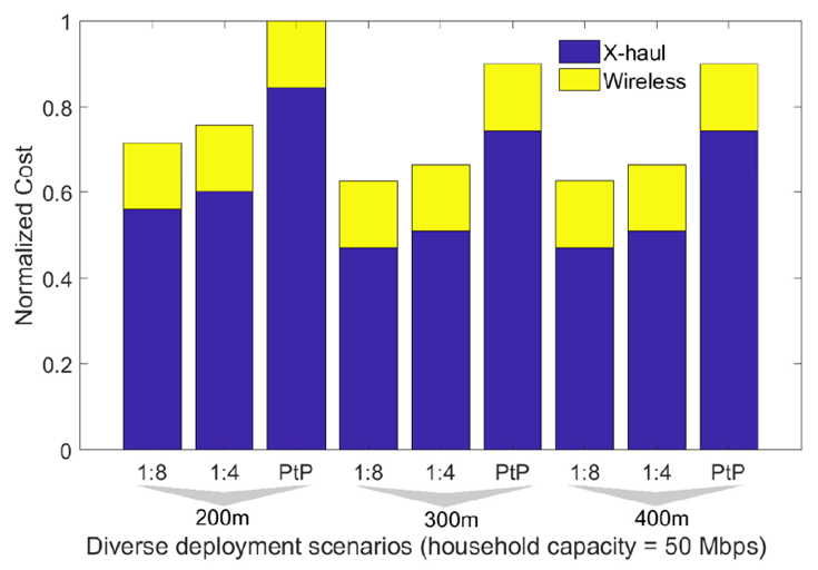
Figure 5. Optimal cost with 10G WDM PON and PtP used as a transport network with coverage 99%
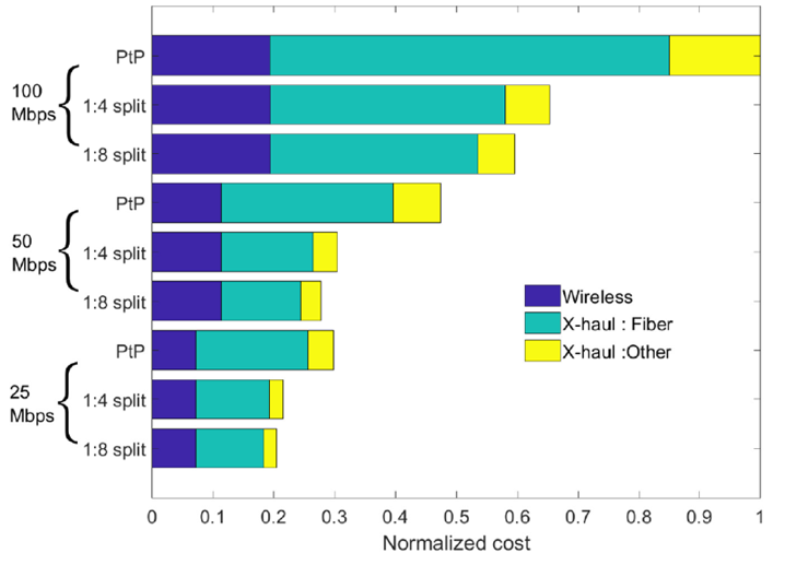
Figure 6. Optimal Cost Vs. Capacity requirement
Figure 6 shows how the deployment cost varies when we have diverse user capacity requirements. We considered a cell radius of 200m and both PtP and 10G PON-based transport network options were analyzed. As expected, the deployment cost increases when the capacity requirement increases. However, the deployment cost of PON-based option is significantly lower compared to the PtP scenario and the cost difference increases with the capacity requirement. For example, at 100 Mbps, the PON-based option saves more than 40% of the deployment cost compared to the PtP case. It is also clear that the main cost contributor among all the deployment scenarios is the installation/use of fiber routes.
After analyzing our results, we have identified that functional split Options 1-6 utilizing PON-based solution can save 30-40% of deployment cost compared to Option 7.2. The details of the evaluation results can be found in [12]. Most importantly, we developed a tool that can be used to optimally plan a 5G/6G and its transport network by simply entering the relevant cost values and the network requirements such as expected coverage percentage, capacity and split ratio.
4. Conclusion
This article highlighted the importance of joint optimal planning of optical transport and wireless networks considering the diverse network requirements in realizing cost-effective deployment of emerging mobile networks. We presented a versatile framework that can be used to provide a cost optimal solution irrespective of the functional split or optical technology in use. The research work presented in the article provide insight into best network design strategies that can be used in planning and dimensioning of optical transport networks for 5G and beyond networks.
References
- M. Agiwal, A. Roy and N. Saxena, "Next Generation 5G Wireless Networks: A Comprehensive Survey," in IEEE Communications Surveys & Tutorials, vol. 18, no. 3, pp. 1617-1655, 2016, doi: 10.1109/COMST.2016.2532458.
- K. B. Letaief, W. Chen, Y. Shi, J. Zhang and Y. A. Zhang, "The Roadmap to 6G: AI Empowered Wireless Networks," in IEEE Communications Magazine, vol. 57, no. 8, pp. 84-90, August 2019, doi: 10.1109/MCOM.2019.1900271.
- X. Liu and F. Effenberger, "Emerging optical access network technologies for 5G wireless [invited]," in IEEE/OSA Journal of Optical Communications and Networking, vol. 8, no. 12, pp. B70-B79, December 2016, doi: 10.1364/JOCN.8.000B70.
- C. Ranaweera, M. G. C. Resende, K. C. Reichmann, P. P. Iannone, P. S. Henry, B-J. Kim, P. D. Magill, K. N. Oikonomou, R. K. Sinha, and S. L. Woodward, ”Design and optimization of fiber optic small-cell backhaul based on an existing fiber-to-the-node residential access network,” in IEEE Communications Magazine, vol.51, no.9, pp.62-69, 2013.
- C. Ranaweera, P. Monti, B. Skubic, M. Furdek, L. Wosinska, A. Nirmalathas, C. Lim, and E. Wong, “Optical X-haul Options for 5G Fixed Wireless Access: Which One to Choose?,” in IEEE
Conference on Computer Communications (INFOCOM), Poster, 2018. - Next Generation Mobile Networks Alliance, NGMN, “Further study on critical CRAN technologies,” White Paper, 2015.
- O-RAN Working Group 1, “O-RAN Architecture Description - v2.00,” O-RAN.WG1.O-RAN-Architecture-Description-v02.00 Technical Specification, July 2020.
- M. Peng, S. Yan, K. Zhang and C. Wang, “Fog-computing-based radio access networks: issues and challenges,” in IEEE Network, vol. 30, no. 4, pp. 46-53, 2016.
- Standardisation, “IEEE 1914.1-2019 - IEEE Standard for Packet-based Fronthaul Transport Networks” April 2020.
- B. Skubic, M. Fiorani, S. Tombaz, A. Furusk¨ar, J. M°artensson, and P. Monti, “Optical transport solutions for 5G fixed wireless access,” in IEEE/OSA Journal of Optical Communication and Networking, vol. 9, no. 9, pp. 10-18, 2017.
- C. Ranaweera, E. Wong, A. Nirmalathas, C. Jayasundara and C. Lim, "5G C-RAN With Optical Fronthaul: An Analysis From a Deployment Perspective," in Journal of Lightwave Technology, vol. 36, no. 11, pp. 2059-2068, 1 June1, 2018, doi: 10.1109/JLT.2017.2782822.
- C. Ranaweera, P. Monti, B. Skubic, E. Wong, M. Furdek, L. Wosinska, C. Mas Machuca, A. Nirmalathas, and C. Lim, "Optical Transport Network Design for 5G Fixed Wireless Access," in Journal of Lightwave Technology, vol. 37, no. 16, pp. 3893-3901, 15 Aug.15, 2019, doi: 10.1109/JLT.2019.2921378.
 Chathurika Ranaweera received her BSc and PhD degrees in Electrical and Electronics Engineering from The University of Peradeniya, Sri Lanka and The University of Melbourne, Australia, respectively. She is currently a senior lecturer at Deakin University, Australia. Her research interests include optical-wireless convergence, optical transport network architectures for 5G/6G, IoT connectivity, network optimization, quality of service management, and Smart Grid communication.
Airborne Free-Space Optical Communications for Fronthaul/Backhaul Networks of 5G and Beyond
Vuong V. Mai and Hoon Kim, School of Electrical Engineering, KAIST, Korea
IEEE Future Networks Tech Focus, Issue 12, April 2021
Abstract
Free-space optical communication (FSOC) provides high-capacity wireless connections, without exhausting scarce RF resources, between airborne platforms constituting aerial fronthaul/backhaul network for 5G and beyond. However, accurate pointing, acquisition, and tracking (PAT) of narrow-divergence optical beams between the transmitter and receiver has long been a major technical challenge of FSOC systems. We introduce an adaptive beam control technique to facilitate the PAT and improve the link availability.
1. Introduction
Airborne platforms are auto-controlled or remotely-operated aerial vehicles operating in high altitudes, such as aerostats, balloons, and drones. The utilization of airborne platforms as a new infrastructure for 5G-and-beyond wireless communication networks has been the subject of considerable interest internationally in recent years [1]-[5]. There are two main reasons for this trend. Ultra-dense heterogeneous small cells are perceived as a key enabler for modern wireless communication networks. In remote areas, however, the installation of terrestrial infrastructure with a large number of small-cell base stations would be highly costly and time-consuming. Airborne platforms, serving as network nodes, can offer substantial benefits in this regard. Also, ultra-high network availability is one of the key motivating trends behind the 5G evolution. In case of emergency or disaster, for example, airborne platforms can undoubtedly provide rapid operational availability for fast bridging and filling network gaps on an ad hoc basis [1].
The 5G network is expected to support 1000-fold increase in data traffic capacity and 10-fold increase in throughput in comparison to 4G systems [6]. To fulfill the expectations, high-speed (e.g., tens of Gbps) communication systems should be realized to transmit massive data traffic between airborne fronthaul/backhaul links. Also, long-distance transmission (e.g., 10 to a few hundred kilometers) is needed to set up the aerial network and improve the network coverage for remote areas. Optical fiber is the best option in terms of data rate and transmission distance among current communication technologies. However, it is not possible to deploy optical fibers for airborne communications. The existing RF and microwave fronthaul/backhaul links rely on frequency bands between 6-60 GHz. However, these bands have been becoming congested in many countries [3]. Limited transmission range and interference with existing terrestrial services are also non-negligible technical issues of RF and microwave technology [2].
The free-space optical communication (FSOC) systems, thanks to their carrier frequency in the range of a few hundreds of THz, can deliver data at a rate of hundreds of Gbps over a long distance. The high carrier frequency also allows FSOC systems to avoid interference problems without exhausting scarce RF and microwave bands. Airborne platforms can be designed to operate in the stratosphere, where the atmospheric conditions are conducive to light propagation. At this high altitude, light scattering and attenuation from clouds, fog, and aerosols are much lower than at the ground level. Thus, FSOC systems could potentially be an ideal option for airborne interconnections, as shown in Fig. 1. 5G data services can be provided to the relatively unexplored regions of the world by constructing an aerial mesh network of airborne platforms placed at an altitude of approximately 20 km or above, where FSOC systems can be used for the interconnections between platforms [4],[5].
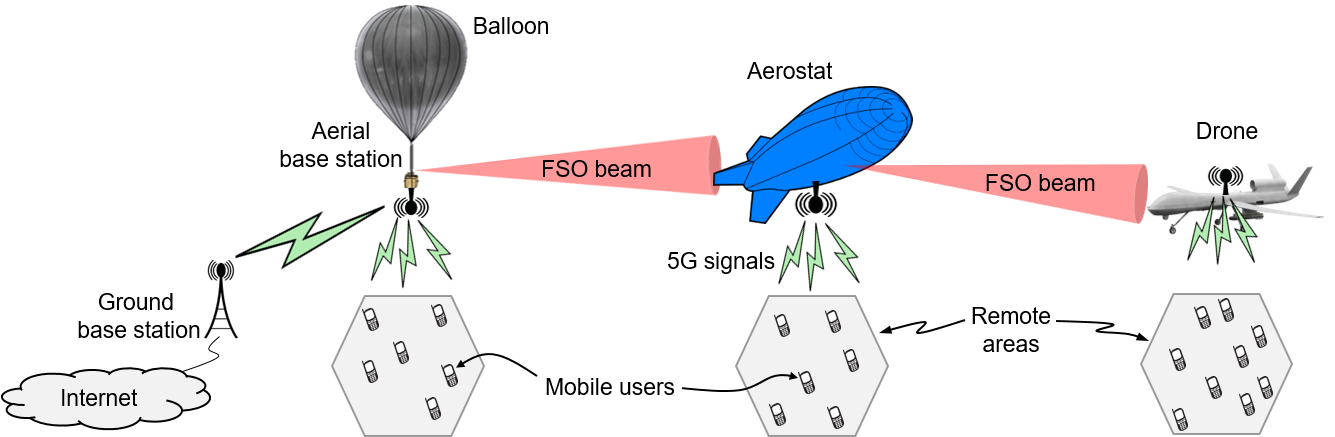
Figure 1. An example of airborne FSOC system for 5G networks.
2. Challenges
The pointing, acquisition, and tracking (PAT) required for airborne FSOC systems is technically challenging due to narrow divergence angle of optical beam and the movements/vibrations of airborne platforms [7]. It is worth mentioning that any PAT techniques should work within tight constraints of airborne platforms on size, weight, and power (SWaP).
The PAT, in general, comprises two phases, coarse and fine PAT. The major role of the coarse PAT is to achieve a rough alignment between the transmitter and receiver. A typical procedure for coarse PAT is to scan an area where the receiver is expected to be located using a beacon light having a relatively large divergence angle. When the receiver detects the beacon signal, it sends the acknowledgment immediately back to the transmitter side. The transmitter employs a separate optical beam with a narrow divergence angle for fine PAT and improves the alignment before sending data to the receiver.
The fine PAT is used to achieve a higher accuracy of the alignment between the transmitter and the receiver. It operates continuously to maintain the alignment. This is because the alignment could be disrupted, for example, by pointing errors and/or angular-of-arrival (AoA) fluctuations. A leading cause of pointing error is transmitter vibrations. Pointing error gives rise to a random movement of beam footprint on the receiver aperture plane. AoA fluctuations could arise from the vibrations at the receiver. They manifest themselves as spot motion or image dancing at the focal plane of the receiver. Thus, both pointing errors and AoA fluctuations severely degrade the performance of FSOC systems during the operation of fine PAT.
Despite the PAT procedure, it is inevitable that there still exists misalignment between the transmitter and receiver, and consequently the received optical signal suffers from frequency-independent fading. This can make or break the link availability of airborne FSOC systems.
3. Solutions
We have recently studied an adaptive beam control technique to facilitate the PAT [8]-[10]. The major purpose of this technique is to enhance the link availability degraded by pointing errors and AoA fluctuations even in the presence of PAT. We propose to employ variable focus lenses to adjust the beam sizes for a practical realization of the adaptive beam control technique. In this scheme, a variable focus lens at the transmitter produces an optical beam having a large divergence angle for coarse PAT. Thus, a single optical beam can be used both for PAT and data transmission. This beaconless scheme could help to simplify transmitter and receiver realization in FSOC systems. For the fine PAT, optimum beam sizes at both transmitter and receiver are realized by using variable focus lenses for mitigating the adverse effects of pointing errors and AoA fluctuations. The major benefits of this realization include that the electrically-adjustable variable focus lens allows the system to be implemented compactly, without resorting to mechanical movements that would be bulky, heavy, and prone to failure. Thus, this scheme would be suitable for airborne applications having tight SWaP constraints.
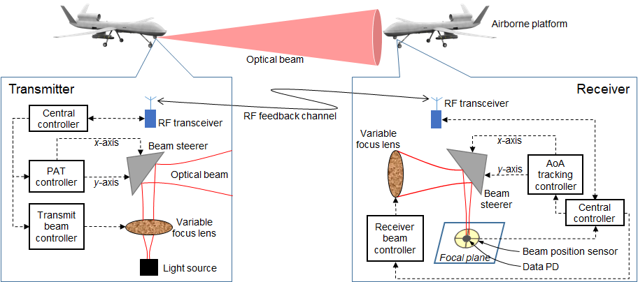
Figure 2. Adaptive beam control technique-based PAT for inter-airborne FSOC systems.
We also propose a new design of the receiver using an integrated beam position sensor and data photo-detector (PD). Besides data detection, this device provides feedback information about the beam location at the receiver, which is used for PAT and adaptive beam control. There are several benefits from the proposed design. First, this integrated device enables a compact design for the receiver. Second, the receiver sensitivity can be improved by the amount of insertion loss of a beam splitter, which is used in typical PAT subsystems. Third, it ensures precision in acquiring information for feedback control since both the sensor and data PD are placed on the same plane. In the conventional design where discrete sensor and data PD are used, an actual beam position of the data signal could be different from the readout from the sensor.
Fig. 2 shows a brief structure of the proposed scheme. At the transmitter, a single light source is employed for both PAT and data transmission. The optical signal generated from the source is first fed to a variable focus lens. The optical beam is then sent to a steering mirror to direct it towards the receiver.
At the receiver, another variable focus lens is used to collect the optical signal. A beam steerer is used to control the direction of the optical beam after the lens. The beam steerer can be implemented by using a fast steering mirror, micro-electro-mechanical systems, liquid crystal, or optical phased array. An integrated beam positioning sensor and data PD is located on the focal plane. In this device, the PD is placed in the middle of the beam positioning sensor. A good example of the beam position sensors is a quadrant detector composed of four PDs. Each of these PDs produces a photocurrent proportional to the power of the incident beam. The quadrant detector has two outputs: one provides the power differences between quadrants, and the other provides the total power detected by the beam position sensor. The former is sent to an AoA tracking controller. This controller adjusts the beam steerer at the receiver to minimize the beam displacement on the focal plane. The latter is sent back to the transmitter through the feedback channel. A low-power radio link, for example, can be used as the feedback channel between the transmitter and receiver. A PAT controller at the transmitter controls the beam steerer at the transmitter based on the feedback information to realize coarse and fine PAT.
It is noted that some information, such as airborne locations, transmit power, size of receiver aperture, and receiver sensitivity, should be exchanged between the transmitter and receiver through the feedback channel before the PAT starts. When the coarse PAT is initiated, the transmit beam size is enlarged. During communications, beam sizes at both transmitter and receiver are adjusted optimally for the system performance based on feedback and local information.
4. Conclusions
Free-space optical communication has the advantages of delivering high-speed data over a long wireless channel without exhausting scarce RF resources. On the other hand, the usage of airborne platforms for the implementation of aerial communication networks offers cost-effectiveness and rapid deployment. Thanks to joining those advantages, airborne FSOC systems could be an essential part of flexible, high-capacity fronthaul/backhaul networks for 5G+. However, the PAT is particularly challenging in inter-airborne FSOC systems. In this regard, the adaptive beam control technique could be applied to support a compact and robust PAT.
Other airborne FSOC systems, such as airborne-to/from-satellite and airborne-to/from-ground communications, could be also considered for 5G+ networks. In this case, there are more arising issues including strong atmospheric turbulence and long-range PAT. In addition to the presented techniques, more research from different fields, such as communications, photonics, and mechanical engineering, should be conducted to address the issues in the future.
Acknowledgment
This work has been supported by the Future Combat System Network Technology Research Center program of Defense Acquisition Program Administration and Agency for Defense Development (UD190033ED).
References
- X. Cao, et al., “Airborne Communication Networks: A Survey,” IEEE J. Sel. Areas Commun., vol. 36, no. 9, pp. 1907-1926, Sept. 2018.
- S. Chandrasekharan, et al., “Designing and Implementing Future Aerial Communication Networks,” IEEE Commun. Mag., vol. 54, no. 5, pp. 26-34, May 2016.
- M. Alzenad, et al., “FSO-Based Vertical Backhaul/Fronthaul Framework for 5G+ Wireless Networks,” IEEE Commun. Mag., vol. 56, no. 1, pp. 218-224, Jan. 2018.
- B. Moision, et al., “Demonstration of Free-Space Optical Communication for Long-Range Data Links between Balloons on Project Loon,” in Proc. SPIE, San Francisco, CA, US, 2017, pp. 100960Z-1-14.
- C. Chen, et al., “High-Speed Optical Links for UAV Applications,” in Proc. SPIE, San Francisco, CA, US, 2017, pp. 1009615-1-9.
- M. A. Adedoyin and O. E. Falowo, “Combination of Ultra-Dense Networks and Other 5G Enabling Technologies: A Survey,” IEEE Access, vol. 8, pp. 22893-22932, Feb. 2020.
- Y. Kaymak, et al., “A Survey on Acquisition, Tracking, and Pointing Mechanisms for Mobile Free-Space Optical Communications,” IEEE Commun. Surveys Tuts., vol. 20, no. 2, pp. 1104-1123, Feb. 2018.
- V. V. Mai and H. Kim, “Adaptive Beam Control Techniques for Airborne Free-Space Optical Communication Systems,” Appl. Opt., vol. 57, no. 26, pp. 7462-7471, Aug. 2018.
- V. V. Mai and H. Kim, “Beam Size Optimization and Adaptation for High-Altitude Airborne Free-Space Optical Communication Systems,” IEEE Phot. J., vol. 11, no. 2, pp. 1-13, Apr. 2019.
- V. V. Mai and H. Kim, “Beam Control and Tracking Techniques for High-Altitude Airborne Free-Space Optical Communication Systems,” in Proc. MWP, Matsue, Japan, Dec. 2020, pp. 1-4.
 Vuong V. Mai (S’12–M’17) received the M.S. and Ph.D. degrees in Computer Science and Engineering from the University of Aizu, Japan, in 2014 and 2017, respectively. In April 2017, he joined the Korea Advanced Institute of Science and Technology (KAIST), Korea, as a Postdoctoral Fellow. He is currently a Research Assistant Professor in the School of Electrical Engineering, KAIST. The primary focus of his current research is on optical wireless technologies and applications.
 Hoon Kim (S’97–A’00–M’04–SM’11) is an Associate Professor of the School of Electrical Engineering at KAIST. Prior to joining KAIST in 2014, he was with Bell Labs, Lucent Technologies (2000~2001), Samsung Electronics, Korea (2001~2007), and National University of Singapore (2007~2014). His research interests include high-capacity fiber-optic communication systems, free-space optical communications, broadband optical access networks, fiber-optic mobile fronthaul/backhaul systems, and lightwave subsystems. He serves as a Senior Editor of IEEE Photonics Technology Letters and an Associate Editor of Optics Express.
Connectivity for Air Mobility Transportation in Future Networks
Saba Al-Rubaye and Antonios Tsourdos, School of Aerospace, Transport and Manufacturing, Cranfield University, UK
IEEE Future Networks Tech Focus, Issue 12, April 2021
Abstract
To enhance safety and efficiency for commercial urban air mobility (UAM) aircraft operation, it is considered that a fully automated data management system will be beneficial to accelerate the widespread commercial deployment of unmanned aircraft systems (UAS). Such operations need to be accommodated in the current national and international controlled airspace as well as in uncontrolled airspace that is currently rarely used for aircraft operations. However, the UAS aircraft demands for ultra-low latency connectivity and reliable operation, especially in city domains is expected to growth to meet the aviation business market. The potential use case presents in this article of six-generation (6G) technology powered by artificial intelligent techniques can contribution to safe and reliable integration of operation services. The new architecture design can facilitate any kind of routine mission in all types of airspace. This can be a roadmap to adopt new aerospace architecture to more sophisticated solutions which offer greater scalability and robust connectivity.
1. Introduction
The future flight is evolving with the arrival of commercial UAS aircraft that provides various services including drone delivery, surveillance of buildings and roads, or even relaying signals for cellular networks. There is an increased recognition of the need to connect remote UAS, to ensure safe and effective operation to the digital economy. The UAS aircraft will operate in lower altitudes within the coverage domains of ground base stations, which required certain features to support regular data transmission along with navigational information required for routing UAS between flying corridors. For UAM domain, the challenge is now being exacerbated by the increased demand for data services, and the more limited range in a terrestrial environment of the higher frequency carriers required for the vertical take-off and landing (eVTOL) systems that provide high user data rates, and the consequential increased infrastructure costs and difficulty of finding suitable locations for deployment. The 6G technology approach offers some of the advantages to the new aerospace architecture by taking advantage of the latest evolutions in fifth generation (5G) end-to-end slicing, artificial intelligence (AI) and Internet-of-Things (IoT) [1]. The 5G operate in two frequency ranges (FRs): FR1 that includes the sub-6 GHz radio frequencies and FR2 that represents the millimetre (mm)-waves operating at higher frequencies between 24.25 - 52.6 GHz. This wide range of radio channels that is most likely to expand into higher bands over the 6G, provided other features, will become the basic infrastructure components for new network that connects UAS and hopefully support the management of their operations.
The UAM simply leverages the unmanned aircraft system into new disciplines that are more associated with human daily life but also requires to fly within crowded urban cities [2]. In wide deployments, UAM poses major safety and security threats unless complemented with intelligent connectivity system that carries UAS acquired data, routing commands, and UAS platform status messages. The state of art for a talented network solution will also require integrating unmanned traffic management (UTM) to manage UAS routing and air transition operations. Tailoring back to network design, capturing data and real-time processing of various parameters become the key factors for over-the-top (OTT) services for UAS-related applications to make decisions, especially UTM. By addressing those complex issues progressively over the coming years, the commercialisation of automated flights and beyond visual line of sight (BVLOS) operations will become less restricted and safe to use at a larger scale. This will open-up the true art of the possible for UAS fleets, particularly in the medical, logistics, energy, and agricultural sectors. This will then enable a shift away from the same repetitive policy making discussions that is most likely to happen at the first deployments towards more proactive decisions that take into account telemetry indicators of both UAS and network platforms as well as tactical changes in UAM traffic status.
In the near future, UAM networks will tremendously evolved driven by a sharp increase in user connected machines, data demands and supported services. Designing a compatible network infrastructure that supports traffic demands in a cost-effective fashion will be always a subject to network generation. A main challenge in providing connectivity to the low flying UASs through future 6G network arises from increased interference. Dense network infrastructure and concurrent transmissions to ground-based users and UASs are the main source for higher noise levels, especially on the downlink. In addition, UASs could also overload the network with massive data streams with limited channel bandwidth. One of the solutions may be drives much tighter frequency reuse and wider channel deployment [3]. Therefore, it is necessary to define the equivalent of hexagonal cellular domain shapes for UAS air layer or what could be the air coverage domains for ground base stations.
2. Integrated UAM and 6G Technology
The existing UTM platforms can support the planning and executing of UAS operations with full compliance to the applicable legislation. It allows the authorities to monitor, track and manage UAS activities within their airspace. UTM services in urban domains are challenged by the highly dynamic topology of airspace, different speeds and sizes of UAS, and heterogeneous quality of service (QoS) requirements (e.g., downlink/uplink, latency, etc.). Therefore, integrating UTM platform into the core/edge data centres of 6G networks will significantly reduce the time delays experienced when data transferred between those systems separately. It will also allow to combine UAS telemetry data with routing information to improve safety and reliability of UAS operations. This integration will solve key challenges faced by content-aware cellular connected aerial platforms including virtualised radio resource sharing and management between aerial platforms and terrestrial systems. This happen due to the fact that both UTM and radio management services are processed concurrently by the same hosting platforms. Obviously, this requires migrating UAM components into virtual automated applications that comply with cloudification concepts and cloud-based network segmentation. The integration of UTM architecture with 6G cellular networks seems to be a mandatory technical requirement a head of deploying UASs at urban areas. Therefore, UAS services may just become a new service slices within 6G to share database required for done identification, localization and performance management.
The 6G trend is expected to leverage current communication technologies using edge computing to visible light as a future solution that can address UAS connectivity problems by providing elastic resources and reliable services to the end users. The proposed high-level diagram shown in Figure 1 does not prevent the existence of more than one UTM, however it assumes that should such operators exist, then all UTM services will coordinate and distribute both constraints and information. It is considered that each of the UAM/UAV operators or systems are independently responsible for the data exchange internally to their own systems, for instance to ensure that appropriate connectivity is maintained between ‘pilots’, operational eVTOL platforms, infrastructure and systems. The 6G communication systems can provide such services are transparent to the UAM/UTM architecture to ensuring a safety. The minimum UAM service portfolio shall include the static and dynamic constraints associated with the geographic areas of exclusion, as specified by the other airspace users, as provided by the air navigation service provider (ANSP). The UTM data management system based 6G platform will help to disseminate information provided by eVTOL or UAS operators and users to other organisations authorised to receive such information, to the level approved for dissemination.
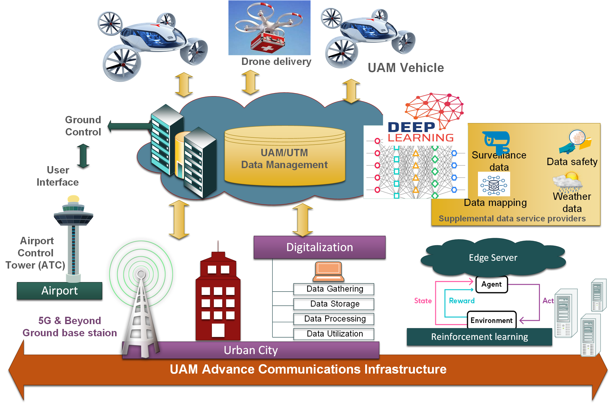 Figure 1. Air mobility operation architecture in 6G paradigm
Regarding the UAM ecosystem, there are several basic data sources that UTM will need to integrate to ensure safe and efficient movement of the UAS. The data could originate from 6G radio access network, UAS service providers, UAS fleets, weather forecasting, surveillance systems, etc. This information is further processed through artificial intelligence (AI) to determine the exact UAS location and relevant traffic managements for that airspace. The UAM service consists of several unmanned systems that can be remotely commanded to perform several tasks including site monitoring, personal security, internet range extension, etc. Requesting a certain service from any UAM platform will be enabled via centralised register that offer such services and identify them to local provider. Although some UAS may support multi-service types and could have differed registers within the database, some will be only associated with one type of services or even owned/operated by one service provider. To this end, services can be classified as separated data repositories that employ their own data processing and storage capabilities. The assignment scheme of services will be highly associated with connectivity model and control commands. A data-driven decision-making approach can be enabled via deep learning data analytics across all the monitored constraints thereby developing a more automated approach for service planning and management, both at strategic and tactical levels. On the other hand, the future 6G networks need to be more focused on using reinforcement learning to understand and learn how to interact with UASs considering requested services and connectivity factors.
3. Autonomy at the Edge
The enrichment of 6G technology will employ sophisticated diagnose and dynamic processing of various events by AI and machine learning, where both can bring unprecedented communication services and experiences to users. The need for intelligent communication network that could support the demand for a higher data rate sufficiently fostered increased interest in the development of drone technology [4]. The AI will be a key component of processing any request for 6G connectivity. This is applicable for future UAM 6G network that employs AI based technology for managing intelligent and ubiquitous connectivity between ground base station and UAS profile through the core network, UTM commands, and platform monitoring through telemetry services, as shown in Figure 2. The deep machine learning provides the prediction mechanism over the entire range of constraints that originate from different data sources. The predications are combined with all real-time data to conduct the necessary adaptions in 6G services, whenever needed. This network design will produce a variety of composable outputs that trigger network optimisation and decision actions. This architecture will also allow 6G networks to provide both real-time analysis and future forensic assessment of connectivity that also reflected in more reliable UAS operations.
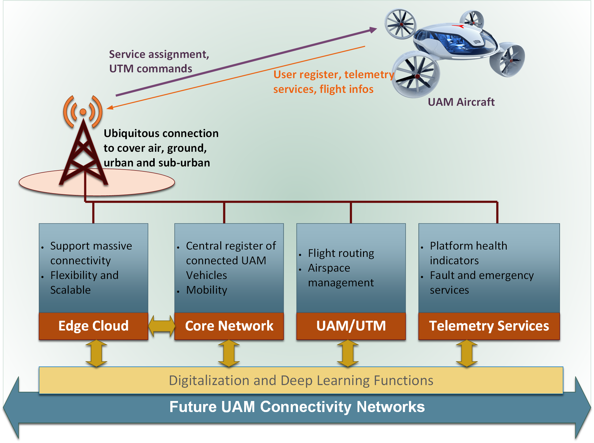 Figure 2. The trend of 6G based AI for future UAM Connectivity
The AI-assisted decisions can be seen in link capacity adaptations to accommodate real-time voice and video transmission from aerial platforms, scalable virtual components that process various requests, changes to flight routes, and notifications on future occurrence of platform alarms. This means that future 6G networks can provide real and futuristic KPIs that support reliable and sophisticated UAS services in urban domains. This article shows how deep learning model explain ability to manage connectivity and flight systems by factoring functional and predicated analysis into network management decisions.
4. Conclusion
This article provided a future flight vision of UAM 6G networks. A high-level architecture that integrates 6G networks with UTM was proposed along with AI-based data processing components. Adopting AI in the UAM 6G formwork requires that multiple applications to operate in real-time on connected virtualization platform that conforms with strict end-to-end KPI requirements of ultra-reliable, ultra-low latency, and massive data processing capabilities. 6G network is shown to bring several benefits to drone technologies regarding the connectivity infrastructure interacts with thousands of UAS and flying taxis through data management system maintains high standards to protect human life. Although these tactics bring several advantages, there are still other challenges and requirement that need to be adopted for UAM to accomplish a real-life capability of such UAS applications to bring connection reliability, network availability, energy efficiency, and security.
Acknowledgments
This research was supported by the grants received from Innovation UK under the programme of Future Flight Challenge- Phase2 (Grants No# 71017, Grant No# 75528 and Grant No#74842)
References
- Tomkos, D. Klonidis, E. Pikasis and S. Theodoridis, "Toward the 6G Network Era: Opportunities and Challenges," in IT Professional, vol. 22, no. 1, pp. 34-38, 1 Jan.-Feb. 2020
- C. Reiche, C. McGillen, J. Siegel and F. Brody, "Are We Ready to Weather Urban Air Mobility (UAM)," 2019 Integrated Communications, Navigation and Surveillance Conference (ICNS), Herndon, VA, USA, 2019, pp. 1-7.
- W. Saad, M. Bennis and M. Chen, "A Vision of 6G Wireless Systems: Applications, Trends, Technologies, and Open Research Problems," in IEEE Network, vol. 34, no. 3, pp. 134-142, May/June 2020,
- T. Han, I. de L. Ribeiro, N. Magaia, J. Preto, A. H. Fontes N. Segundo, A. Roberto L. de Macêdo, K. Muhammad, and V. Hugo C. de Albuquerque., "Emerging Drone Trends for Blockchain-Based 5G Networks: Open Issues and Future Perspectives," in IEEE Network, vol. 35, no. 1, pp. 38-43, February 2021.
 Saba Al-Rubaye received her Ph.D. degree in Electrical and Electronic Engineering (Telecommunications) from Brunel University London. Currently, she is working as a Senior Lecturer and leading connected system research and development in DARTeC at Cranfield University. Her main research interests focus on air mobility communications, autonomous system, aircraft connectivity, and 5G/6G systems. She is a Chartered Engineer (CEng) and Senior Member of IEEE.
 Antonios Tsourdos received his Ph.D. on nonlinear robust missile autopilot design and analysis from Cranfield University. He is currently a Professor in Autonomous Systems and Control. He is the head of Autonomous and Cyber-Physical Systems Centre and Director of Research at Cranfield. He has extensive expertise in both unmanned and autonomous vehicles as well as networked systems. He conducts basic and applied research in the fields of guidance, control and navigation as well as research on future flight.
IEEE Tech Focus - April 2021
IEEE Future Networks Tech Focus
Issue 12, April 2021
In This Issue
- Airborne Free-Space Optical Communications for Fronthaul/Backhaul Networks of 5G and Beyond
- Rethinking of Optical Transport Network Design for 5G/6G Mobile Communication
- CSAI: Open-Source Cellular Radio Access Network Security Analysis Instrument
- Connectivity for Air Mobility Transportation in Future Networks
Airborne Free-Space Optical Communications for Fronthaul/Backhaul Networks of 5G and Beyond
April 2021
Vuong V. Mai and Hoon Kim, School of Electrical Engineering, KAIST, Korea
ree-space optical communication (FSOC) provides high-capacity wireless connections, without exhausting scarce RF resources, between airborne platforms constituting aerial fronthaul/backhaul network for 5G and beyond. However, accurate pointing, acquisition, and tracking (PAT) of narrow-divergence optical beams between the transmitter and receiver has long been a major technical challenge of FSOC systems. We introduce an adaptive beam control technique to facilitate the PAT and improve the link availability.
Rethinking of Optical Transport Network Design for 5G/6G Mobile Communication
April 2021
Chathurika Ranaweera, Deakin University, Australia
Ampalavanapillai Nirmalathas, Elaine Wong, Christina Lim, The University of Melbourne, Australia
Paolo Monti, Marija Furdek, Lena Wosinska, Chalmers University of Technology, Sweden
Björn Skubic, Ericsson Research, Sweden
Carmen Mas Machuca, Technical University of Munich, Germany
Driven by the increasing use of emerging smart mobile applications, mobile technology is continuously and rapidly advancing towards the next generation communication systems such as 5G and 6G. However, the transport network, which needs to provide low latency and reliable connectivity between hundreds of thousands of cell sites and the network core, has not advanced at the same pace. This article provides insight into how we can solve the fundamental challenges of implementing cost-optimal transport and 5G and beyond mobile networks simultaneously while satisfying the network and user requirements irrespective of the radio access network's architecture.
CSAI: Open-Source Cellular Radio Access Network Security Analysis Instrument
April 2021
Thomas Byrd and Vuk Marojevic, Mississippi State University
Roger Piqueras Jover*, Bloomberg LP
This paper presents our methodology and software toolbox that allows analyzing the radio access network security of laboratory and commercial 4G and future 5G cellular networks. We leverage a free open-source software suite that implements the LTE UE and eNB enabling real-time signaling using software radio peripherals. We modify the UE software processing stack to act as an LTE packet collection and examination tool. This is possible because of the openness of the 3GPP specifications. Hence, we are able to receive and decode LTE downlink messages for the purpose of analyzing potential security problems of the standard. This paper shows how to rapidly prototype LTE tools and build a software-defined radio access network (RAN) analysis instrument for research and education. Using the Cellular Security Analysis Instrument (CSAI), a researcher can analyze broadcast and paging messages of cellular networks. CSAI is also able to test networks to aid in the identification of vulnerabilities and verify functionality post-remediation. Additionally, we found that it can crash a software eNB which motivates equivalent analyses of commercial network equipment and its robustness against denial of service attacks.
Connectivity for Air Mobility Transportation in Future Networks
April 2021
Saba Al-Rubaye and Antonios Tsourdos, School of Aerospace, Transport and Manufacturing, Cranfield University, UK
To enhance safety and efficiency for commercial urban air mobility (UAM) aircraft operation, it is considered that a fully automated data management system will be beneficial to accelerate the widespread commercial deployment of unmanned aircraft systems (UAS). Such operations need to be accommodated in the current national and international controlled airspace as well as in uncontrolled airspace that is currently rarely used for aircraft operations. However, the UAS aircraft demands for ultra-low latency connectivity and reliable operation, especially in city domains is expected to growth to meet the aviation business market. The potential use case presents in this article of six-generation (6G) technology powered by artificial intelligent techniques can contribution to safe and reliable integration of operation services. The new architecture design can facilitate any kind of routine mission in all types of airspace. This can be a roadmap to adopt new aerospace architecture to more sophisticated solutions which offer greater scalability and robust connectivity.
Progress and Challenges in the Cellular Industry and 5G
Qi Bi, China Telecom
IEEE Future Networks Tech Focus, Volume 4, Issue 1, November 2020
Abstract
When compared with the 4G-LTE, 5G has made impressive progress in many technological areas including the spectral efficiency, user data rate, and transmission delay. It promises to support mMTC and uRLLC in addition to the traditional eMBB. However, by examining the 5G system operating in the field, this paper intends to provide insights that show different sides of 5G that we have not seen, and uncover issues that need to be addressed in the future.
1. Progress made by 5G
The technology of 5G has made impressive progress in many areas including the spectral efficiency, data rate, transmission delay, and system capacity [1-3], despite difficulties [4] The following table shows the 5G targets as provided by ITU [5]. While the metrics of this table are well advertised by the media and business conferences, a little known secret is that some of these metrics were not actually achieved. As can be seen from the table, the 8 metrics could be divided into three categories: achieved, achievable and not achieved.
|
Achieved by 5G |
Achievable by 5G |
Not Achieved |
||||||
|
mobility |
User speed |
Efficiency |
Density |
Connection |
Delay |
Energy |
Peak rate |
|
|
4G |
350Km/h |
10 Mbps |
1x |
0.1 Mbps/m2 |
100,000/km2 |
10ms |
1x |
1Gbps |
|
5G |
500Km/h |
100Mbps |
3x |
10 Mbps/km2 |
1million/Km2 |
1ms |
100x |
20Gbps |
When labeled as achievable, this means that the target has not yet been achieved because there is no need. When the system capacity and density requirements increase, the target can be achieved by simply investing more money to purchase more equipment.
In the “not achieved” category, there exists the energy efficiency and peak rate targets. The target for 100 times the efficiency was vague to begin with and was overly optimistic because it was based purely on theoretical wishes. The 20Gbps peak rate, however, is based on the assumption that more than 1GHz bandwidth is available and that the peak rate spectral efficiency would be adequate. Currently, only 100-200MHz are typically available for sub-6GHz bands and only about 800MHz are available for 28GHz bands. Further, the peak rate efficiency in high bands was significantly lower due to the limitations on the chipset and hardware processing power.
In spite of the peak rate gap, 5G has made significant progress in terms of Shannon’s information theory guidance [6-7] as given in the following chart.
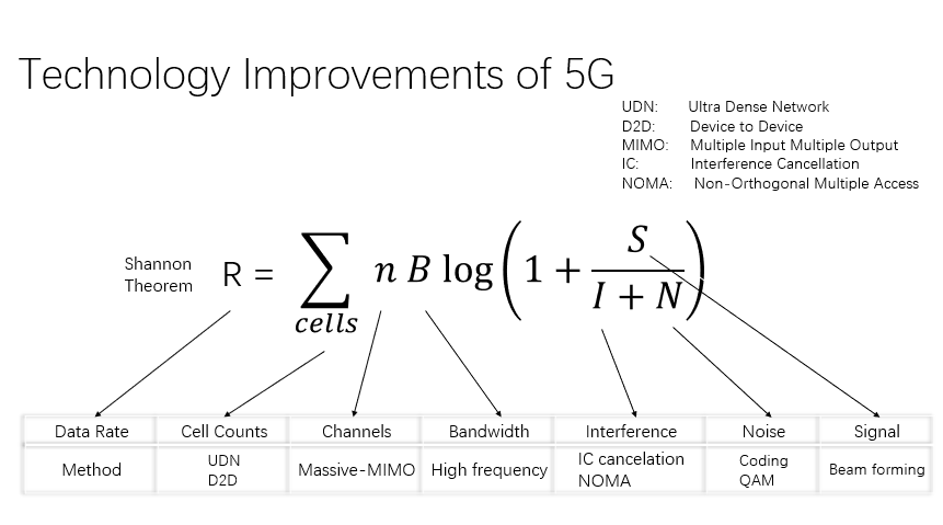
Figure 1
By examining each of the innovations as seen above, massive MIMO can be identified to provide most of the gains for 5G. The spectral efficiency and the peak rate efficiency of the wireless system evolution are provided in the following two charts.
In China, China Telecom has been granted 100MHz license in the 3.5GHz spectrum. 5G trials in this band were carried out and the achievable peak rates in 100MHz is provided in the following chart, which shows that about 1.5Gbps can be expected for the DL and less than 300Mbps may be obtainable for the UL under the best RF conditions if the system has only a single user.
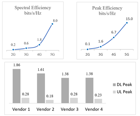
Figure 2
2. Challenges of 5G
While progress made by 5G has been impressive, 5G also faces many challenges [8] as we shall discuss below.
2.1. Revenue challenge of 5G
While the progress made by 5G is impressive, its deployment is not believed to improve the financial income of operators in terms of ARPU, as was the case for the past generations. This assumption can be easily derived from the figure below in which the historical ARPU curve was provided by one of the world’s largest operators from the second largest economy in the world. In the above figure, it can be observed that China Telecom’s ARPU followed a downward slope even after the company aggressively invested in new system evolution from 2G to 3G and then to 4G that improved the data rate immensely for large number of users. Consequently, it is reasonable to predicted that the impressive data rate improvement from 5G will unlikely to increase the ARPU for China Telecom. This trend appears to be applicable to operators worldwide.
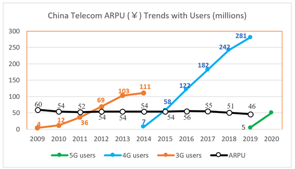
Figure 3
The above facts prompted efforts to expand 5G capabilities beyond the traditional eMBB service. These capabilities include mMTC and uRLLC. Despite good intentions, the progress made on the ground is not as satisfactory for reasons as will be discussed in the follow sections.
2.2. Cost challenge for 5G
One of the main features for 5G is the massive MIMO that has significantly improved the spectral efficiency and data rate. As a result of the massive MIMO, the cost of the 5G base station is more than two times that of 4G. Due to the fact that 5G will be operating at the higher band, its system would require more base stations, which would put pressure on the CAPEX investments of operators. To accommodate the wider band for 5G, a higher transmission power of 200W was adopted to maintain the power density similar to that of 4G that uses a typical 60W. This 3-fold increase in transmission power will likely translate into 3 times the electric bill required by each base station for 5G. Since the electric expense is a significant percentage of an operator’s OPEX, this electric consumption is a serious issue that will need to be dealt with in the future.
2.3. Millimeter wave challenge of 5G
In order to meet the growing demands for data rates and system capacity, next generation cellular systems have consistently moved to higher frequencies to satisfy the broader bandwidth requirements. For 5G, two frequency bands are defined as FR1 and FR2 where FR2 is the millimeter wave band. The propagation loss of the radio waves in a free space can be determined by the distance and transmission frequency as given in the following formula [9]:
where c is a constant, Dt is the transmit antenna gain, Dr is the receive antenna gain, f is the transmission frequency and d is the radius from the transmitter. When considering other propagation environments, the COST model [10] indicates that the exponent increases from 2 to about 3.5. From this, it can be determined that a ten-fold increase in frequency would result in a similar amount of decrease in the propagation radius if the pathloss of the system is kept the same for a similar QoS.
To counter this drastic radius reduction, antenna technology is typically used to increase the antenna gain by taking advantage of the fact that the size of the antenna is proportional to the wavelength. By keeping the antenna size about the same for each generation, the loss caused by being at the high bands can be partially compensated by increasing the number of antennas.
However, due to the fact that the antenna gain improvement requires an exponential increase in the number of antennas and the fact that the chipset complexity improvement for each generation cannot follow the required increase in the number of antennas, the number of base stations required to have ubiquitous coverage at the millimeter wave bands are costly prohibitive. Consequently, millimeter wave deployment is only considered for hot spot or for special applications such as fixed wireless application. This use case affects the volume of the millimeter wave base stations and therefore the cost of the system, which has made the millimeter wave deployment much less successful globally.
Another challenge of the millimeter wave deployment for 5G is a result of the world politics. As previously discussed, the drastic effect on coverage when moving to higher bands can be partially mitigated by increasing the number of antennas which would in turn increase the complexity and the cost of the system and devices. The trend in the industry is such that the ARPU and the device cost curves have remained flat for each generation.
For this reason, the common practice for keeping the cost in check is by handling the device complexity increase with the increase of the device volume in the markets. This strategy has worked in the past but may have hit a roadblock in the millimeter wave case. Due to the fact that the millimeter wave technology was initially used for satellite and military purposes similar to the GPS system, there are still export restrictions for millimeter wave devices that are no present for GPS technology. As a result, GPS has been successfully commercialized globally whereas the prevalence of the millimeter wave deployments for 5G may depend on the removal of the restrictions if the volume and cost of such deployments are expected to reach the desired level.
2.4. Transmission delay challenge in 5G
To achieve the expected high data rate for 5G, larger bandwidth is needed that can only be found in higher bands. As a result, time division duplex (TDD) is the prevailing choice over FDD because a paired spectrum is harder to find. However, one problem with the TDD is that the UL and DL need to take turns to transmit, introducing an additional link switch transmission delay. Furthermore, due to the fact that a time gap is needed between the UL and DL to allow signal transition, this switch between the UL and DL cannot be done too often in order to minimize the time gap for efficiency consideration. As a result, TDD would result in a non-negligible transmission delay depending on efficiency considerations.
As an example, China Telecom and China Union have jointly decided to use 2.5ms TDD configuration as a compromise between the delay and the capacity efficiency. This results in an additional link switch transmission delay of 2ms. From this example, it appears that even though the 5G standard has defined configurations that could meet the 1ms transmission target by ITU, in practice this target cannot be achieved in the real world due to capacity efficiency considerations. To support the 1ms target for uRLLC applications, China operators have deployed FDD systems that avoid the link switch delay. This, however, requires operators to deploy FDD systems for low delay applications in addition to the TDD system for high data rate eMBB applications.
2.5. Coverage and data rate challenge for 5G
In the previous section, it was discussed that the coverage shortcoming from moving to the higher bands could partially be compensated for by increasing the number of antennas. Another trend in the next generation system such as 5G is to move from FDD which uses the paired channel to TDD which uses a single band. This change in the duplex, however, introduces about 5 dB additional loss on the UL which would also need to be compensated.
To understand this, consider the TDD configuration as adopted by China Telecom and China Unicom for example. The time slot configuration is given in the following figure.
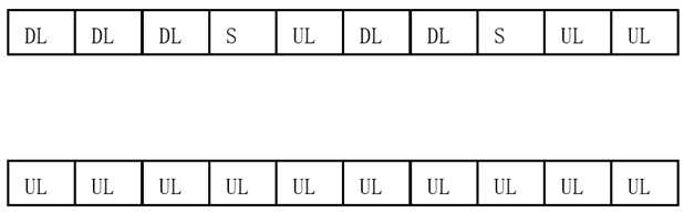
Figure 4: TDD time slots divided for DL and UL (Top), FDD time slots all for UL (Bottom)
In the above figure, each DL, UL or S time slot is 0.5ms. Each time slot consists of 14 sub-slots. For special time slot labeled as S, 10 of its 14 sub-slots are assigned to DL, 2 are assigned as gap sub-slots for transition, and 2 sub-slots are assigned for the UL. Therefore, the total UL sub-slots for TDD system are (3x14) + (2x2) = 46 out of 140, which is about 33% in time domain. In comparison, the transmission at 2.1GHz band using FDD can dedicate all time slots for UL transmission. If the maximum terminal transmits powers of both TDD and FDD are identical, clearly the receiver would lose 66% of time to accumulate the energy in the TDD case, resulting in about 5 dB loss for the TDD system when compared with that of the FDD system.
Currently most terminals are equipped with two simultaneous transmitters. While more than two are possible in the future, but two may still be a preferred choice for most handsets due to the cost consideration.
From the above figure, if the terminal assigns both transmitters to TDD operation, it could enjoy the 5G peak rate from the 100MHz bandwidth with two antenna MIMO technology, but it suffers a 5 dB coverage loss. If any of the two transmitters uses the FDD transmission mode with 20MHz bandwidth, the coverage gain is obtained at the cost of the data rate obtainable via two TDD transmitter antennas. To solve this dilemma, China Telecom proposed the use of multi-carrier time division duplex technique which combines the operation of the TDD with the FDD. With this proposal, the two transmitters are allowed to switch quickly at each 0.5ms boundary that is not possible for Release 15 of 5G. Time slots of 1, 2, 3, 4, 6, 7 and 8 are allowed to transmit the UL signals using FDD operation. At the time slot 5, 9, and 10, the two transmitters will all be assigned to TDD to take the advantage of 100MHz bandwidth. This combined TDD and FDD innovation from China Telecom solves this FDD and TDD dilemma and will be available in Release 16 of 5G [12-13].
2.6. mMTC challenge for 5G
Given the flat ARPU discussed previously, mMTC was the hope to provide additional revenue growth for operators. While this seems logic and attractive, the reality so far appears disappointing. The first attempt to support mMTC was done in 4G-LTE using the narrow band technology known as the NB-LTE or NB-IoT. China Telecom was the first operator in the world to have deployed the commercial NB-LTE system in large scale. So far, China Telecom has not yet obtained the expected revenue from the NB-LTE launch, whereas NTT DoCoMO in Japan went a step further by terminating its NB-LTE operation after only one year in operation [11]. Clearly the road to success for IoT may be long and arduous.
When analyzing the requirements for mMTC, the important factors for success include coverage, cost, and system platform. Since 5G will operate at a higher band than LTE, the increased path attenuation goes against the coverage requirement. For the cost, general electronic market trends indicate that new technology equipment and devices are always much more expensive initially and then decay rapidly with time. Therefore, 5G is not necessarily a better choice than 4G or even 3G for IoT application in terms of the cost. Furthermore, IoT applications are diverse and require different hardware and software platforms which take a long time to mature. Because of the slower than expected growth, not much effort is being made to develop new standard in 5G for IoT. 3GPP currently recommends NB-LTE for IoT applications. Consequently, the much hyped eMBB, mMTC and uRLLC applications of 5G will actually require three different hardware systems to support, namely a TDD system for eMBB, a FDD system for uRLLC and a NB-LTE system for mMTC.
2.7. Network slicing challenge in 5G
Because vertical applications are important for 5G to improve financial revenues for operators, one feature advertised heavily is the network slicing capability [14]. While the network slicing is a brilliant idea to deliver differentiated QoS to meet the diverse needs of the vertical industries, there is a disconnection between the core network and the radio access network (RAN) for this capability. The reason for this is that the concept of slicing in 5G has been limited only to the core network and does not have the corresponding implementation in RAN. More specifically, the diverse needs of the vertical applications in RAN are still being handled by using the QoS indices that remain largely unchanged since 3G. The inflexibility of QoS mapping based on applications rather than on users, locations and time of the services has significantly diminished the power of the network slicing. As a result, the network slicing cannot at all guarantee the end-to-end quality required by vertical applications. This makes the network slicing a limited value at best for vertical applications.
2.8. Industrial module challenge for 5G
One key factor for the success of vertical applications for 5G is the cost and the flexibility of the terminals or industrial modules.
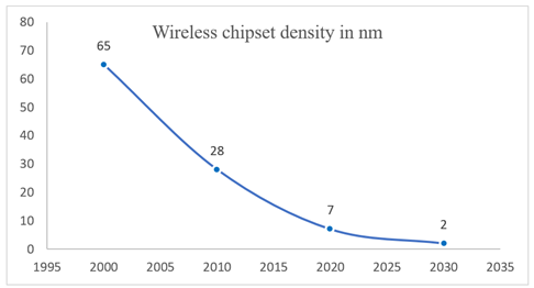
Figure 5
As can be seen from the above figure, 3G utilized 65nm technology for the chipset, 4G utilizes 28nm. For 5G, initial chipset utilizes 7nm technology. The second-generation chipset for 5G will utilize 5nm technology. The increased cost and complexity of the chipset is mitigated by increased chipset sales in each generation. However, the cost of the chipset may still be too expensive for vast of the vertical applications. Furthermore, this level of chipset density makes it prohibitively expensive for any chipset modifications to meet the diverse needs of the vertical applications. For this reason, 3GPP has launched “5G light” effort in the standard process to reduce the complexity and cost for industrial terminals or modules. Will “5G-light” be successful in solving the cost issue for the vertical application modules, only time can tell.
3. Conclusions
5G has made significant progress in user data, transmission delay and system capacity. Although attempts are made to reverse the declining revenue trend for operators by supporting vertical applications, challenges remain formidable in areas of costs, coverage, QoS flexibility, fractured markets, and the maturity of vertical platforms. The success of the millimeter wave deployment may additionally depend on removal of the export restrictions to promote a healthier global ecosystem and to further reduce the system and device costs.
References
- GSMA website, https://www.gsma.com/r/mobileeconomy/
- G.J.Foschini and M.J. Gans, "On Limits of Wireless Communications in a Fading Environment when Using Multiple Antennas", Wireless Personal Communications, vol.6,pp.311-335, 1998.
- Erik G. Larsson ; Ove Edfors ; Fredrik Tufvesson ; Thomas L. Marzetta, “Massive MIMO for next generation wireless systems,” IEEE Communications Magazine, Volume: 52 , Issue: 2 , February 2014.
- M. Dohler; R.W. Heath; A. Lozano; C.B. Papadias; R.A. Valenzuela, “Is the PHY layer dead?” IEEE Communications Magazine, Volume: 49, Issue: 4, April 2011, pp. 159 - 165
- M.2083, "IMT Vision - Framework and overall objectives of the future development of IMT for 2020 and beyond," ITU-R M.2083, 2015.
- Shannon, Claude E. and Warren Weaver. “The Mathematical Theory of Communication.” Urbana, Illinois: University of Illinois Press, 1949.
- Berrou, Claude; Glavieux, Alain; Thitimajshima, Punya, “Near Shannon limit error-correcting coding and decoding: Turbo-codes,” Proceedings of ICC '93 - IEEE International Conference on Communications, May 1993.
- QI BI. Ten Trends in the Cellular Industry and an Outlook on 6G. IEEE Communications Magazine, 2019,57(12): 31-36.
- https://en.wikipedia.org/wiki/Free-space_path_loss
- https://en.wikipedia.org/wiki/COST_Hata_model
- https://www.mobileworldlive.com/featured-content/top-three/docomo-kills-off-nb-iot-network/
- TR21.916, “3GPP Release 16 Description,” https://www.3gpp.org/release-16, July, 2020
- RP-192251, “Proposal on UE requirements to allow switching between two uplink carriers,” Submission to 3GPP TSG RAN #85, Newport Beach, USA, September, 2019.
- P. Popovski et al., “5G Wireless Network Slicing for eMBB, URLLC, and mMTC: A Communication-Theoretic View,” IEEE Access, vol. 6, Sept. 2018, pp. 55,765–79.
Biography
Qi Bi is the Chief Expert of China Telecom with interests in 5G and 6G responsible for technologies, standards and trials. He received his M.S. from Shanghai Jiao Tong University and Ph.D. from Pennsylvania State University.
Previously, Dr. Bi worked at Bell Labs for 20+ years and was awarded the prestigious Bell Labs Fellow in 2002. Other awards included Bell Labs President’s Gold Awards in 2000 & 2002, the Bell Labs Innovation Team Award in 2003, and Asian American Engineer of the Year in 2005. He is an IEEE Fellow, and served in the IEEE Fellow evaluation committee for the communication society in 2017-2019. He holds 47 US patents, 63 European patents and 65 Chinese patents. While in China Telecom, his 4G innovation project was successfully deployed in 75% of China Telecom’s markets and won the GTB Innovation Award at London in 2014.
An Overview of 3D Printed Antennas for 5G Communications and Beyond
Henry Giddens, and Yang Hao, Queen Mary University of London
IEEE Future Networks Tech Focus, Volume 4, Issue 1, November 2020
Abstract
5G communication systems will once again revolutionize the ways that people connect and communicate with each other. Future mobile networks will also span new frequency bands in mm-wave and THz bands. The combination of the need to wirelessly connect everyday consumer devices to the internet, and the range of new frequency bands on offer, has necessitated research into new antenna systems. One technology that is enabling the realization of a new class of antennas is 3D printing. This has been fueled in part by the rise of new antenna design techniques such as transformation optics and topological optimization, whilst further developments in new filament materials designed specifically for electromagnetic applications means complex antenna geometries can now be easily realized. This article presents an overview of the ways in which additive manufacturing is enabling the development of novel antennas for 5G wireless networks and beyond.
1. Introduction
The 5th generation of mobile communications will once again offer vast improvements in bandwidth and coverage, which will translate into a user experience of fast download speeds and an uninterrupted connection to the network. The antennas used in these networks will need to facilitate these features whilst maintaining low profile and conformal physical dimensions so that they can be included in consumer devices and access points. At the mm-wave bands, directive communications is essential to overcome the higher path loss and steerable beams will be required to communicate with mobile targets. Future communication networks will look to utilize even high frequencies, approaching the THz bands and sub-millimeter wavelengths. Antennas will also have to support wide input-impedance bandwidths, whilst maintaining good radiation efficiency and reliable radiation patterns. In this article we look at how 3D printing is addressing these issues. The rapid rise and falling cost of 3D printing technology over the last 10 years has generated a growing industry estimated to be worth over $10 billion in 2020 [1]. In technology-focusses industries this has manifested itself in small-scale manufacturing and rapid prototyping of new de- vices. In recent years, antenna research has taken advantage of the possibilities offered by additive manufacturing techniques. For example, antennas with complex spacial material profiles can now be realized with various 3D printing techniques. Furthermore, new design techniques for conformal antennas such as transformation optics and multi-objective topological optimization are being utilized which are particularly suited to generating printable antennas [2], [3]. Metallic printing has allowed engineers to manufacture new types of antennas up to THz frequencies, whilst 3D printing has also contributed to the realization of microwave metamaterial antennas.
2. Materials and Printing Techniques
A number of 3D printing techniques have been used for printing antenna and electromagnetic structures. These include fused deposition modeling (FDM), also known as fused filament fabrication (FFF), Polyjet printing, stereo lithography (SLA), micro-SLA and photonic polymerization. Each method has advantages and trade-offs which are suited to manufacturing different types of antennas. For example, FDM, where filament materials are extruded from a heated nozzle, is generally the cheapest 3D printing technique available, whilst it also benefits from a wide variety of filaments and can print with multiple materials in a single print. The SLA and polymerization techniques use laser or UV light to cure resin materials into the desired 3D shape. As a result, they can achieve a much higher resolution when compared to FDM, down to the 10s of nanometers scale. They are better suited to fabrication of smaller structures, and therefore are used to fabricate antennas operating in mm-wave and THz frequency bands. The materials used in these printers are essentially a light curable resin, and subsequently cannot be modified to the extent that FDM filaments have been.
3D printing has most commonly been used for manufacturing dielectric-based antennas. This is due to the fact that printing dielectric materials is far easier than printing conductive filaments. Dielectric materials can be printed using fused deposition modeling (FDM) 3D printers that can be purchased for just a few hundred dollars, whilst standard filament materials such as ABS (Acrylonitrile butadiene styrene, a common thermoplastic) and PLA (polylactic acid, a biodegradable thermoplastic polyester) have been shown to have low dielectric losses up to 100s of GHz [4]. Furthermore, specialized dielectric filaments are available for electromagnetic (EM) applications with tailored dielectric constants up to a value of 12 [5]. Fig. 1 shows the measured dielectric properties of a selection of Preperm filaments for two mm- wave frequency bands, 70-110 GHz and 220-320 GHz. All filaments are stable with frequency and the losses only become significant for the highest permittivity materials when the frequency exceeds 200 GHz.
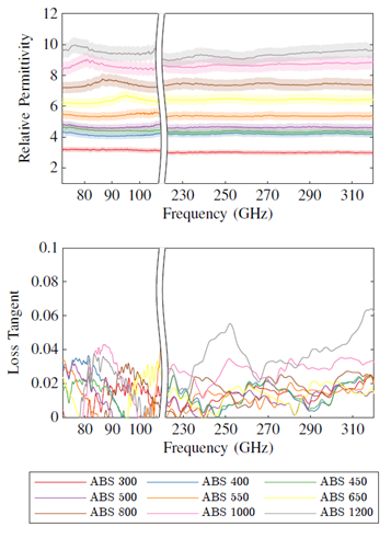
Figure 1. Measured relative permittivity and loss tangent of electromagnetic dielectric filaments available from PREPERM [5] at mm-wave frequencies. The filaments were printed using a Prusa i3 MK3s 3D printer into 20 x 20 mm samples with 100% fill factor and measured using a quasi-optical transmissometer. The shaded area shows the error boundary associated with the measured data.
Antennas with gradient-index material profiles (i.e. materials that have spatially varying dielectric properties) are uniquely suited to 3D printing for a number of reasons. From the effective-medium theory it is possible to predict the effective permittivity of a volume of material where only a percentage of that volume is filled with a dielectric filament, and the rest of the volume by air. 3D printed dielectric metamaterials can easily be printed to obtain precise effective permittivity, and this can be further varied throughout the total volume of the antenna to obtain graded-index materials so long as the unit cell dimensions are significantly smaller than the wavelength. Multi-material 3D printing can be used to extend both the range and steepness of the dielectric gradient which opens up new possibilities in the antenna design [6].
3. Dielectric Antennas
Due to the ease of printing dielectrics compared to conductive materials, 3D printing is best suited to fabricating dielectric antennas such as lenses and DRAs. Lens have been demonstrated using almost all the common 3D printing methodologies spanning a wide range of frequencies from microwaves through the mm-wave bands and up to THz. Lens antennas are particularly suited to mm-wave 5G frequency bands as they generate directive radiation, are not physically large due to the small wavelength, and can also have beam steerable capabilities, whilst the wavelength is not so small as to be beyond the resolution of FDM 3D printers. The Luneburg lens for example, is a multi-focal lens able to concentrate a plane wave impeding on any surface to a point on the opposite surface of the lens, requires a material profile with permittivity of 2 in the center and 1 on the surface [7], as shown in Fig. 2 (a - c). Whilst the Luneburg lens has been known to optical engineers since it was proposed by Rudolf Luneburg in 1944, 3D printing has offered a simple solution for easy fabrication. In order to adapt the Luneburg lens and make it more practical for real-world applications, various geometrical modifications to the Luneburg lens have been demonstrated through trans- formation optics coordinate transformations. These include the Gutman lens Fig. 2 (d-f) [8], the compressed Luneburg lens Fig. 2 (g - j) [9], and the flat Luneburg lens [10]. Each of these modifications requires a more complex material profile, however they can be realized using the 3D printing techniques previously described. Each modification to the Luneburg lens importantly retains the key feature of generating directive, steerable beams which are necessary for 5G mm-wave and future THz communication links. Fig. 2 shows some examples of the various Luneburg Lenses which have been 3D printed for mmWave beam scanning applications. The lenses are often excited using traditional antenna elements such as patches, waveguide probes and horns, with the lens taking the role of shaping and steering the antenna beam.
Lens antennas at THz frequencies will form a key element in THz communication systems as they are wideband devices and generate the directive beams necessitated by the small wavelength and high path loss. 3D printed THz lenses have been demonstrated through micro SLA 3D printing, which are able to print with sub-micron resolution [11] that is require to generate graded-index interfaces at THz wavelengths. A number of diffractive lenses operating at 0.625 THz were demonstrated in [12] using low cost 3D printing techniques.
3D printing has also been use to realize antennas in specialist radios where customized designs are required. For example, an 8-beam lens operating in military mobile-adhoc networks with multi-functionality and 360° coverage was presented in [6]. The lens, shown in Fig. 3, is able to radiate with an optimized 45° beamwidth in each of its 8 sectors, but can switch to multi-beam mode covering 8 directions in any one instance due to the symmetry of the lens. The lens was 3D printed using multi-material printing with a permittivity gradient ranging from 3.6 on the edge to 1 in the center, and takes a conformal octagonal shape.
Dielectric resonator antennas offer unique advantages over traditional antennas, such as a reduced size whilst maintaining a wide input impedance bandwidth and good radiation efficiency, which can be beneficial to 5G communications networks. 3D printing has also opened up new possibilities in dielectric resonator antenna research. For example, the gradient-index DRA presented in [13] and shown in Fig. 4 excites three transverse modes which are merged together to provide a wide input impedance bandwidth from 4 - 8 GHz. 3D printed DRA arrays have also been demonstrated as high- gain access point antennas [14], and the technology has been further applied to mm-wave frequencies [15].
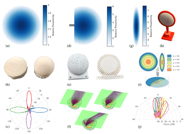
Figure 2. An overview of beam steerable 3D printed lens antennas for mmWave communications. (a) - Permittivity distribution of a classic Luneburg lens antenna [7]. (b) - Photograph of 3D printed Luneburg Lens antenna using effective medium theory. (c) - Measured radiation patterns at 28 GHz with feed position at 0◦, 90◦, -90◦, and 180◦. (d) - Permittivity distribution of the Gutman lens with the focal point moved to a position of 0.45R [8]. (e) Photograph of the 3D printed Gutman lens at 60 GHz. (f) - Simulated electric field patterns showing beam steering as the feed position is moved along the flat face of the lens. (g) - Permittivity distribution of a compressed Luneburg lens [9]. (h) - photograph of the 3D printed compressed Luneburg lens at 84 GHz. (i) - Setup for multi-material 3D printing of the compressed lens with 5 different filaments. (j) - Measured radiation patterns of the compressed lens at 84 GHz. All measurements and fabrication of lens antennas performed at Queen Mary University London.
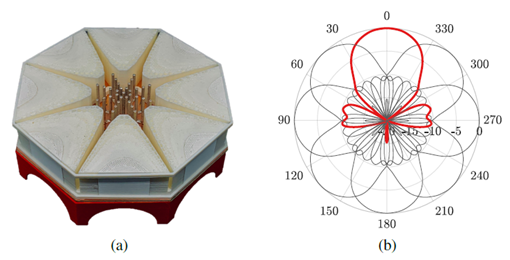
Figure 3. 3D-printed 8-beam dielectric lens antenna with multi-functionality including optimized 45° radiation pattern [6].
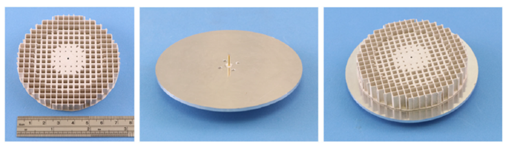
Figure 4. A graded-index 3D-printed dielectric resonator antennas with 3 transverse modes and wide input impedance bandwidth [13].
4. Metallic Antennas
Most traditional antenna structures require a conductive element in order to interface with the input port and provide resonance. 3D printing conductive materials for electromagnetic applications remains a challenging problem for a number of reasons. Poor conductors, which are acceptable for 3D printed electronic circuits, are not suited to antenna applications as the losses severely impact radiation efficiencies. However, conductive filaments have recently become commercially available which may offer some potential, such as the Multi3D Electrificonductive filament with a quoted volume resistivity of 0.006 Ω cm [16]. For purely metallic antennas, specialist metal 3D printers are an alternative option. These can directly print the metallic materials including aluminum, steel, titanium and cobalt through direct metal laser sintering (DMLS). For example, Jun et. al. 3D printed fractal monopole antennas (Fig. 5) using metal AM which have ultra-wideband radiation characteristics and geometries that would be difficult to realize using subtractive manufacturing methods [17]. Metallic printing has also been used to fabricate horn antennas and waveguides at 110-170 GHz [18], although surface roughness and layer height can become an issue at submillimeter wavelengths. Metallic printing is likely to be widely utilized to fabricate mmWave and THz antennas that required intricate 3D geometries that traditional techniques are incapable of achieving.
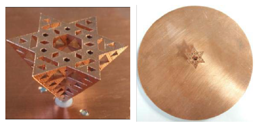
Figure 5. Fractal monopole antenna using metallic AM technology [17].
An alternative and cost effective approach for 3D printing metallized antenna parts is to print using a regular filament or resins, and then coat the parts in conductive materials [19–22]. This allows the intricate and detailed 3D shapes associated with additive manufacturing techniques to be incorporated into antenna technologies, has a much lower material cost than pure metal antennas, and has other advantages in terms of weight [21]. 4 different coating techniques, Jet Metal Processing (JMT), aerosol spray coating using copper and nickel conductive paints, and brush painting with electrolube silver conductive paint, were analyzed in [20]. JMT is able to achieve performance comparable to PEC antennas at both 10 GHz and 30 GHz. Metal-coated 3D printed parabolic mirrors have also been demonstrated with nanometer scale surface roughness for THz applications [22]. Low cost metallization techniques clearly offer possibilities for mass production of low cost 3D printed antennas for 5G, mm-wave and THz communications.
5. Metamaterials
Metamaterials are artificially designed periodic structures which can be designed to have properties which are not found in naturally occurring materials. Electromagnetic metamate- rials have been demonstrated with negative refractive index components for applications such as cloaking. Metamaterials can also be utilized in more practical applications including wireless communication. 3D printing is a valuable tool for further innovation in this field, as it allows multiple materials to be combined in complex structures that will give an optimal material response. For example, a chequerboard dielectric metamaterial with anisotropic properties was 3D printed in [23] using two high-contrast dielectric filaments. The authors in [24] 3D printed a broadband microwave metamaterial with customized permittivity and permeability using the electrificonductive filament.
6. Summary
In summary, it is clear that 3D printing has already had a significant impact on antenna related research and development. With incoming 5G networks and trends for future communications systems moving to higher frequencies, additive manufacturing technology will become increasingly important to the industry. It is expected that widely available and low cost 3D printing techniques, such as FDM and SLA, as well as the more specialist additive manufacturing methods, including Nano-scale photonic printers and metallic 3D printing, will all contribute to the continued development and manufacture of novel antennas for wireless networks.
References
- “Global 3D printing industry market size,” library Catalog: www.statista.com. [Online]. Available: https://www.statista.com/ statistics/315386/global-market-for-3d-printers/
- O. Quevedo-Teruel, W. Tang, R. C. Mitchell-Thomas, A. Dyke, H. Dyke, L. Zhang, S. Haq, and Y. Hao, “Transformation optics for antennas: why limit the bandwidth with metamaterials?” Scientific Reports, vol. 3, no. 1, p. 1903, May 2013.
- T. Maruyama, K. Yamamori, and Y. Kuwahara, “Design of Multibeam Dielectric Lens Antennas by Multiobjective Optimization,” IEEE Trans- actions on Antennas and Propagation, vol. 57, no. 1, pp. 57–63, Jan. 2009.
- J. M. Felcio, C. A. Fernandes, and J. R. Costa, “Complex permittivity and anisotropy measurement of 3D-printed PLA at microwaves and millimeter-waves,” in 2016 22nd International Conference on Applied Electromagnetics and Communications (ICECOM), Sep. 2016, pp. 1–6.
- “3D Filaments for Quick Prototyping,” library Catalog: www.preperm.com. [Online]. Available: https://www.preperm.com/ webshop/product-category/3d-filaments/
- H. Giddens and Y. Hao, “Multi-Beam Graded Dielectric Lens Antenna from Multi-Material 3D Printing,” IEEE Transactions on Antennas and Propagation, pp. 1–1, 2020.
- R. K. Luneburg, Mathematical Theory of Optics. University of California Press, 1966, google-Books-ID: VIZAy68oFiMC.
- A. S. Gutman, “Modified Luneberg Lens,” Journal of Applied Physics, vol. 25, no. 7, pp. 855–859, Jul. 1954.
- A. Demetriadou and Y. Hao, “Slim Luneburg lens for antenna applica- tions,” Optics Express, vol. 19, no. 21, pp. 19 925–19 934, Oct. 2011.
- C. Mateo-Segura, A. Dyke, H. Dyke, S. Haq, and Y. Hao, “Flat Luneburg Lens via Transformation Optics for Directive Antenna Applications,” IEEE Transactions on Antennas and Propagation, vol. 62, no. 4, pp. 1945–1953, Apr. 2014.
- F. Zhou, W. Cao, B. Dong, T. Reissman, W. Zhang, and C. Sun, “Additive Manufacturing of a 3D Terahertz Gradient-Refractive Index Lens,” Advanced Optical Materials, vol. 4, no. 7, pp. 1034–1040, 2016.
- W. D. Furlan, V. Ferrando, J. A. Monsoriu, P. Zagrajek, E. Czerwiska, and M. Szustakowski, “3D printed diffractive terahertz lenses,” Optics Letters, vol. 41, no. 8, pp. 1748–1751, Apr. 2016.
- Z.-X. Xia, K. W. Leung, and K. Lu, “3-D-Printed Wideband Multi-Ring Dielectric Resonator Antenna,” IEEE Antennas and Wireless Propaga- tion Letters, vol. 18, no. 10, pp. 2110–2114, 2019.
- A. A. Althuwayb, K. A. Abdalmalak, C. S. Lee, G. Santamara-Botello, L. E. Garca-Castillo, D. Segovia-Vargas, and L. E. Garca-Muoz, “3-D- Printed Dielectric Resonator Antenna Arrays Based on Standing-Wave Feeding Approach,” IEEE Antennas and Wireless Propagation Letters, vol. 18, no. 10, pp. 2180–2183, 2019.
- D. C. Lugo, R. A. Ramirez, J. Castro, J. Wang, and T. M. Weller, “3D printed multilayer mm-wave dielectric rod antenna with enhanced gain,” in 2017 IEEE International Symposium on Antennas and Propagation USNC/URSI National Radio Science Meeting, Jul. 2017, pp. 1247–1248, iSSN: 1947-1491.
- “Electrifi Conductive Filament.” [Online]. Available: https://www. multi3dllc.com/product/electrifi/
- S. Y. Jun, B. Sanz-Izquierdo, E. A. Parker, D. Bird, and A. McClelland, “Manufacturing Considerations in the 3-D Printing of Fractal Antennas,” IEEE Transactions on Components, Packaging and Manufacturing Tech- nology, vol. 7, no. 11, pp. 1891–1898, Nov. 2017.
- B. Zhang, Z. Zhan, Y. Cao, H. Gulan, P. Linnr, J. Sun, T. Zwick, and H. Zirath, “Metallic 3-D Printed Antennas for Millimeter- and Submillimeter Wave Applications,” IEEE Transactions on Terahertz Science and Technology, vol. 6, no. 4, pp. 592–600, Jul. 2016.
- S. Alkaraki, A. S. Andy, Y. Gao, K.-F. Tong, Z. Ying, R. Donnan, and C. Parini, “Compact and Low-Cost 3-D Printed Antennas Metalized Using Spray-Coating Technology for 5G mm-Wave Communication Systems,” IEEE Antennas and Wireless Propagation Letters, vol. 17, no. 11, pp. 2051–2055, 2018.
- S. Alkaraki, Y. Gao, M. O. Munoz Torrico, S. Stremsdoerfer, E. Gayets, and C. Parini, “Performance Comparison of Simple and Low Cost Metallization Techniques for 3D Printed Antennas at 10 GHz and 30 GHz,” IEEE Access, vol. 6, pp. 64 261–64 269, 2018.
- D. Shamvedi, O. J. McCarthy, E. O’Donoghue, P. O’Leary, and R. Raghavendra, “Improving the Strength-to-Weight Ratio of 3-D Printed Antennas: Metal Versus Polymer,” IEEE Antennas and Wireless Propagation Letters, vol. 17, no. 11, pp. 2065–2069, 2018.
- N. Vaidya and O. Solgaard, “3D printed optics with nanometer scale surface roughness,” Microsystems & Nanoengineering, vol. 4, no. 1, pp. 1–8, Jul. 2018.
- D. V. Isakov, Q. Lei, F. Castles, C. J. Stevens, C. R. M. Grovenor, and P. S. Grant, “3D printed anisotropic dielectric composite with meta- material features,” Materials & Design, vol. 93, pp. 423–430, Mar. 2016.
- Y. Xie, S. Ye, C. Reyes, P. Sithikong, B.-I. Popa, B. J. Wiley, and S. A. Cummer, “Microwave metamaterials made by fused deposition 3D printing of a highly conductive copper-based filament,” Applied Physics Letters, vol. 110, no. 18, p. 181903, May 2017.
Biography
Yang Hao is a Professor of Antennas and Electromagnetics at Queen Mary University of London. He also serves in the management team of Cambridge Graphene Centre since 2013. He is active in a number of areas, including computational electromagnetics, microwave metamaterials and transformation optics, antennas and radio propagation for body centric wireless networks, active antennas for millimeter/sub-millimeter applications and photonic integrated antennas. He co-published two books: “Antennas and Radio Propagation for Body-Centric Wireless Communications”, and “FDTD modelling of Metamaterials: Theory and Applications”. He has published more than 200 journal papers and is a frequent keynote speaker for many conferences. Prof. Hao was the Editor-in-Chief for the IEEE ANTENNAS AND WIRELESS PROPAGATION LETTERS. He founded a new open access journal and is now the Editor-in-Chief of EPJ Applied Metamaterials.
He won 2015 IET AF Harvey Research Prize and is a co-recipient of BAE Chairman’s Silver Award in 2014 and the Royal Society Wolfson Research Merit Award. Prof. Hao is an elected Fellow of Royal Academy of Engineering, IEEE and IET.
Professor Yang Hao received the Ph.D. degree from the Centre for Communications Research (CCR) at the University of Bristol, U.K. in 1998. From 1998 to 2000, he was a postdoc research fellow at the School of Electrical and Electronic Engineering, University of Birmingham, U.K.
Delivering on 5G’s Foundational Control Requirements
Jim Ross, MIPI RF Front-End Control Working Group chair
IEEE Future Networks Tech Focus, Volume 4, Issue 1, November 2020
Abstract
5G will bring great changes to wireless communications—and, by extension, the Internet of Things and all of the industrial, automotive and other application areas that rely on the technology. Control for the Radio Frequency Front-End of the wireless components that enable these application areas is an important element to bring order to the 5G story. The MIPI Alliance, an international organization that develops interface specifications for mobile and mobile-influenced industries, recently updated its MIPI RF Front-End Control Interface—MIPI RFFE—with emphasis on supporting the next wave of 5G applications around the world.
1. Introduction
To realize the anticipated impact of the fifth generation of technology standards for cellular networks, it is important to focus on and anticipate the needs of the Radio Frequency (RF) marketplace today.
The RF front end is an important aspect of 5G and wireless communications. The RF subsystems that connect to the modem baseband and/or RF integrated circuit transceiver—antenna tuners, filters, low-noise amplifiers (LNAs), power amplifiers, switches—rely on the RFFE control architecture. The MIPI Alliance RF Front-End Control Interface (MIPI RFFE) is deployed in virtually every device with cellular connectivity that is being manufactured around the world [1].
Version 3.0 of the MIPI RFFE specification, released in May 2020 [2], was streamlined and optimized to deliver the functionality that system architects, original equipment manufacturers (OEMs), and device vendors need to advance new 5G use cases across the Frequency Range 1 (FR1) of traditional sub-6 GHz cellular bands. 5G renders the RF front-end with a significantly more complex and challenging environment to orchestrate; however, MIPI RFFE simplifies configuration, integration and multi-vendor interoperability across the wireless components enabling the Internet of Things, industrial, automotive and other application areas leveraging 5G networks.
2. Consolidating Interfaces
MIPI RFFE is emblematic of the types of core standard interfaces that MIPI Alliance was formed in 2003 to design, enabling mobile device manufacturers to source components from multiple vendors, optimize their devices and accelerate rollout to end users.
MIPI’s founding came at a critical juncture in the evolution of the RF marketplace. While there was clearly a market for smart, multimedia handsets, product design and development were hindered by industry fragmentation across essential interface technologies. Four companies—ARM Limited, Nokia Corporation, STMicroelectronics, and Texas Instruments Incorporated—founded the MIPI Alliance to consolidate interfaces. Four more companies—Intel Corporation, Motorola, Inc., Philips and Samsung Electronics, Co.—joined within a year. Working groups were formed, and MIPI’s first specifications—facilitating the interconnection of cameras, displays and modems to application processors—were introduced.
By 2008, the MIPI Alliance had grown to 150 members representing all facets across the mobile ecosystem, from semiconductor firms to OEMs. Seven more specifications were introduced, addressing a range of essential needs. The MIPI RF Front-End Control Working Group was formed during this time to address the specific needs of the RF front end.
Today, the MIPI Allance numbers more than 325 members. Dozens of MIPI specifications [3] serve six types of interface needs in a device: physical layer, multimedia, chip-to-chip/interprocessor communications (IPC), device control and data management, system debugging and software integration. Each specification is designed to deliver the fundamental performance characteristics of low power to preserve battery life, high bandwidth to enable feature-rich, data-intensive applications, and low electromagnetic interference (EMI) to minimize interference among radios and device subsystems. All of the world’s major chip vendors rely on MIPI specifications, and its specifications are utilized in hundreds of millions of smartphones.
3. Delivering Order, Simplifying Design and Deployment
When the MIPI RF Front-End Control Working Group was formed, many vendors were making multiple versions of the same device just so they could operate within the different environments of various OEMs.
First released in July 2010, MIPI RFFE defines a compact, cost-efficient and flexible two-wire control bus interface for RF subsystems. See figure 1. The MIPI interface brings order to the RF front-end environment, abstracting away interconnect and feature complexity by applying common control mechanisms to the various, multi-vendor mobile components which enable the cellular, IoT, industrial, automotive and other applications.
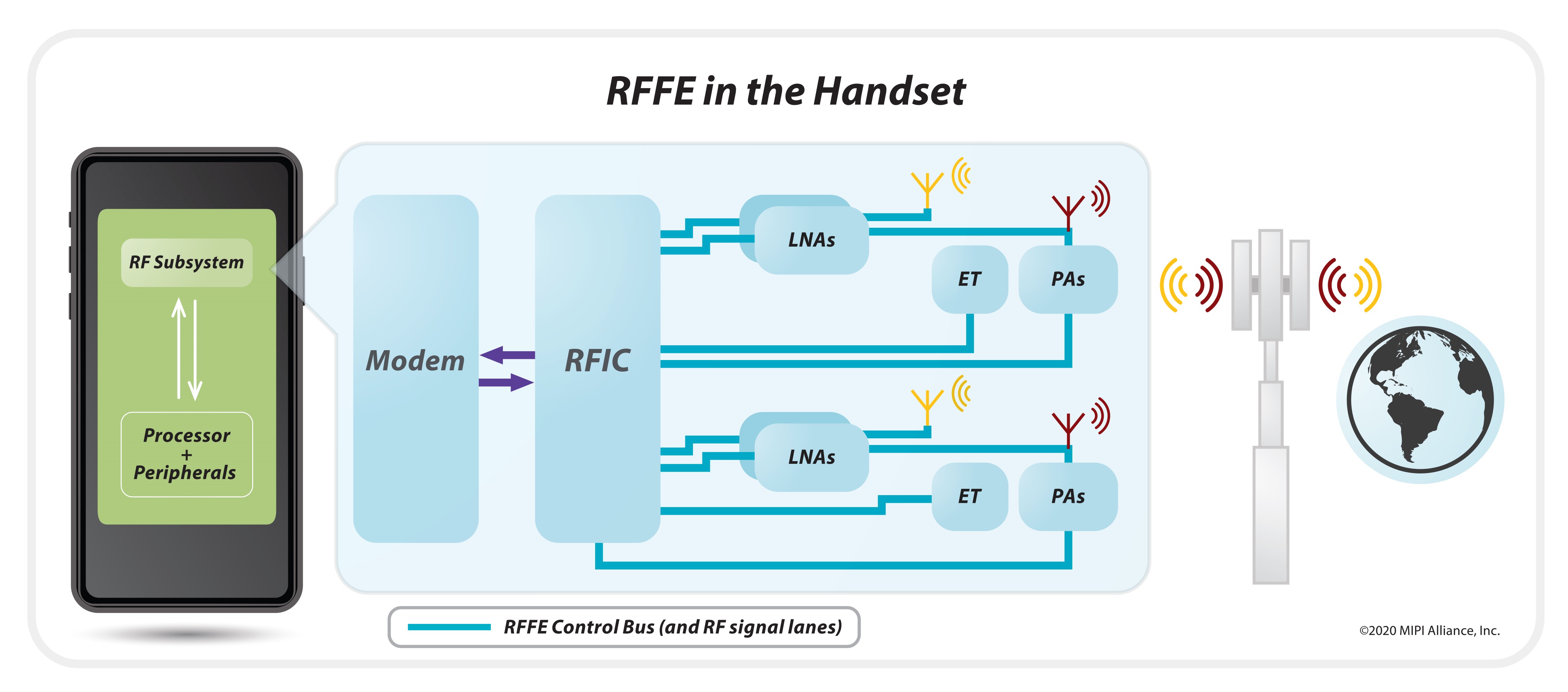
Figure 1: MIPI RFFE deployed in mobile handsets.
MIPI RFFE is deployed across handsets, smartwatches, automobiles and other devices using wireless connectivity worldwide. As RF front-end designs have grown steadily more complicated with more components to be linked and synchronized, the interface has been regularly updated over the years to address new market opportunities and challenges.
4. Moving Into Application Spaces Beyond Mobile
The MIPI RFFE Working Group developed RFFE v3.0 to eliminate challenges the early days of 5G rollout have introduced for RF system architects in terms of collisions of disparate RFFE command sequences.
5G evolution has increased the complexities for RF control. Higher-order multiple-input/multiple-uutput (MIMO) resource sharing introduces new complexities for the system architects. Timing budgets are shortening. The data rates of 5G complicate control of the RF front end from a number of perspectives:
- Increased number of available bands
- Decreased symbol/slot intervals for reduced latency
- More carrier-aggregation combinations
As a former RFFE Working Group colleague, John Oakley, wrote for Tech Design Forum [4]:
“Smartphones and tablets have conditioned people to expect that they can have access to any information they want instantly, anytime and anywhere. Fast wireless network technologies such as LTE and IEEE 802.11ac are helping to meet that expectation. Fifth-generation cellular standards will raise the bar for designers tasked with enabling such instant gratification, by pushing download speeds into the Gigabit per second range and latencies into single-digit milliseconds.
This combination of rising user expectations and continuous network improvements creates major challenges for systems designers, who must find ways to keep their devices from becoming the bottleneck. …”
The new version of MIPI RFFE streamlines and refines the specification, enabling the more nimble configuration changes within and across RF subsystems that 5G demands through enhanced and expanded “trigger” functionality. See figure 2. Triggers basically give the RF subsystem the ability to configure multiple RF devices with very tight timing control and have been a key feature of MIPI RFFE since its initial release. But, to adapt for the smaller reconfiguration windows and enable lower-latency switching among various bands and band combinations defined in the 3GPP 5G standard, the working group in v3.0 specified a larger set of complementary trigger features for synchronizing and scheduling register-setting changes.
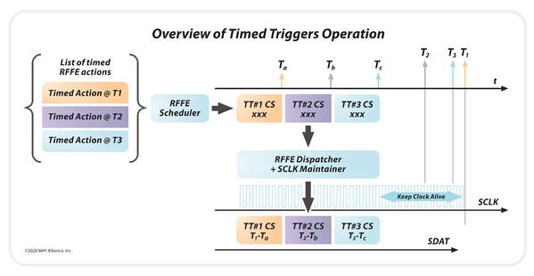
Figure 2: Overview of MIPI RFFE v3.0 enhancements to the interface’s trigger features and functionality.
RFFE v3.0’s timed, mappable, and extended triggers work together to improve throughput efficiency, cut packet latency and transform timing precision. Timing precision for back-to-back triggering operations is boosted by 20x in the new release. In this way, the MIPI specification successfully addresses 5G’s heightened timing requirements presented by the FR1 of traditional sub-6 GHz cellular bands.
5. Conclusion
MIPI RFFE v3.0 is backward compatible with prior versions of the RFFE specification, so OEMs and device vendors can migrate systems without overhauling the interface’s physical layer to pursue the 5G business opportunities of today. The RFFE working group is discussing proposals for the next version of the specification, which will be intended to address the challenges that the Frequency Range 2 will introduce, and anticipate possible 6G network evolution requirements for the RF front end.
The working group always is looking for additional contributors and new ideas. In particular, we are seeking more input from the system side of the RF industry. Please learn more and engage.
References
- https://mid.mipi.org/
- https://mipi.org/MIPI-RFFE-v3.0-Delivers-Features-for-Successful-5G-Rollouts
- https://www.mipi.org/mipi-alliance-specifications
- J. Oakley, “Using the MIPI RFFE specification to simplify the control architecture of multi-radio SOCs,” Tech Design Forum, Jan. 31, 2017.
Biography
A long-time member of the MIPI Alliance, Jim Ross has been active on the RF Front-End Control Working Group since its inception in 2008 and has served as its chair since 2011. Prior to that he was vice chair of the group from 2008 to 2011.
Mr. Ross serves as technical director for the mobile solutions business at Skyworks Solutions, Inc. (Nasdaq: SWKS) an innovator of high-performance analog semiconductors connecting people, places and things. In this role, he is the technical lead and designer for the digital content of Skyworks products specific to the MIPI RFFE interface for all of the Company’s business units. A digital designer in the communications industry since 1992, he previously worked in design engineer roles at Conexant Systems and Rockwell Collins.
Mr. Ross received his Bachelor of Science and Master of Science degrees in electrical engineering at the University of North Dakota.